Bearing device

a bearing and bearing technology, applied in the direction of bearings, shafts and bearings, rotary bearings, etc., can solve the problems of sliding bearing damage, deformation part coming,

Active Publication Date: 2015-11-24
DAIDO METAL CO LTD
View PDF13 Cites 2 Cited by
  • Summary
  • Abstract
  • Description
  • Claims
  • Application Information

AI Technical Summary

Benefits of technology

[0011]In a case of a bearing device in which a bearing housing made of an Al alloy is used, since the bearing housing made of the Al alloy has a larger thermal expansion coefficient than that of a Fe alloy back metal layer of a sliding bearing, as a temperature of the bearing device becomes lower, a difference between a contraction amount of an inside diameter (inner circumferential length) of a bearing holding hole of the bearing housing and a contraction amount of an outside diameter (outer circumferential length) of the sliding bearing becomes larger and compressive force in a circumferential direction to be received with the sliding bearing becomes larger.
[0013]Thus, an object of the present invention is to provide a bearing device in which deformation of a circumferential direction end of a sliding bearing toward a bearing inside diameter side is suppressed.
[0033]When the bearing device of the present invention is placed under low temperature condition in cold districts and the like, compressive force in the circumferential direction to be received with the sliding bearing press-fitted into the bearing holding hole of the bearing housing made of the Al alloy becomes larger, and the outside diameter (circumferential length) of the sliding bearing is elastically deformed to be small. The sliding bearing of the bearing device of the present invention includes the plurality of hardened convex portions, hardened concave portions, and hardened areas on the circumferential direction ends, and thus an elastic deformation amount of a non-hardened area occupying the most part of the cylindrical portion of the sliding bearing except for the areas of the circumferential direction ends becomes relatively smaller. Therefore, one of or both of the circumferential direction ends of the sliding bearing are prevented from swelling to be deformed toward the inside diameter side of the sliding bearing. Accordingly, the circumferential direction end of the sliding bearing is less likely to swell toward the inside diameter side and come in contact with the shaft to be damaged.

Problems solved by technology

If operation of the bearing device is started in this state, the deformation part comes in contact with a shaft and the sliding bearing may be damaged (see FIG. 10).

Method used


Image

  • Bearing device
  • Bearing device
  • Bearing device

Examples


Embodiment Construction

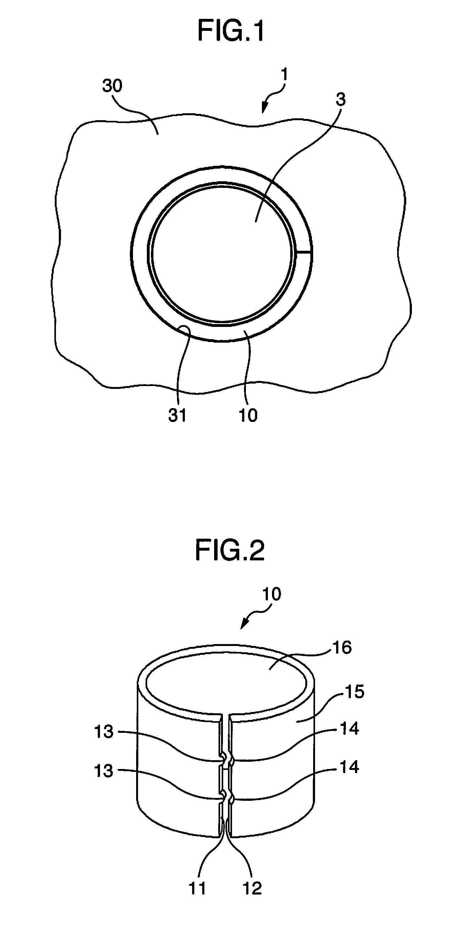
[0050]FIG. 1 illustrates a bearing device 1 of a first embodiment of the present invention. A bearing housing 30 is made of an Al alloy and has a bearing holding hole 31, and a sliding bearing 10 is press-fitted into the bearing holding hole 31. A shaft 3 is supported with an inner circumferential surface of the sliding bearing 10 (surface of a sliding layer 16). As the Al alloy of the bearing housing, a typical Al alloy for casting, such as an Al—Si alloy, an Al—Si—Cu alloy, and an Al—Si—Cu alloy can be used.

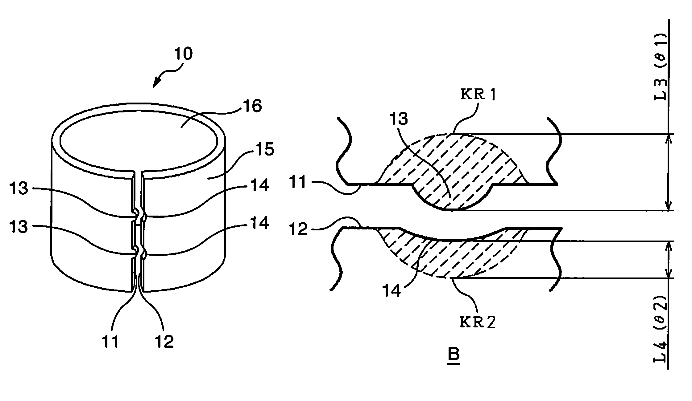
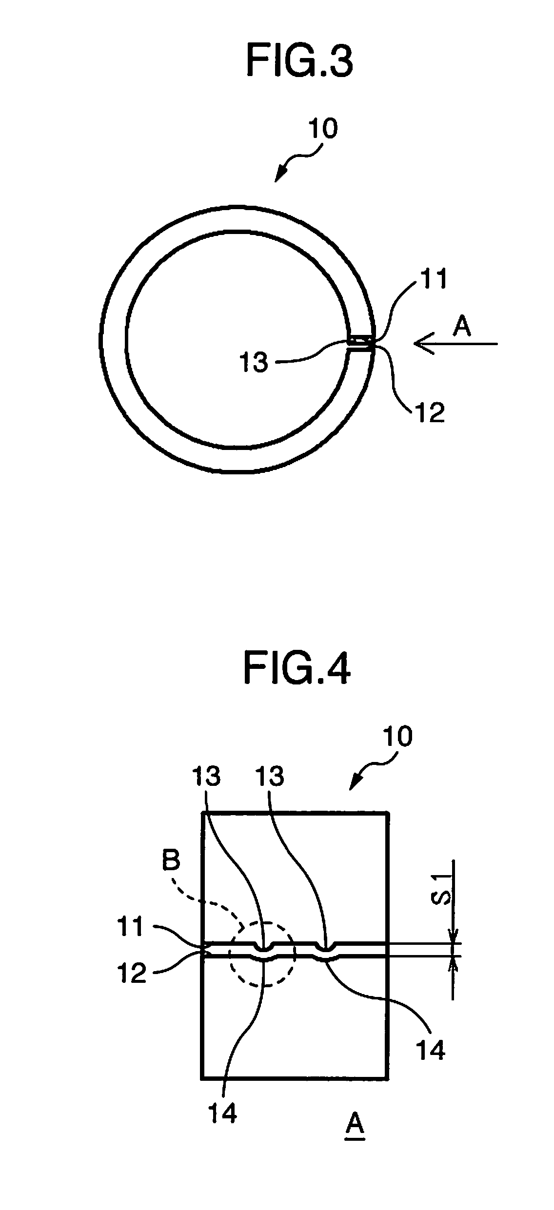
[0051]As illustrated in FIG. 2, the sliding bearing 10 has a cylindrical shape and includes a Fe alloy back metal layer 15 on an outside diameter side of the cylindrical shape and the sliding layer 16 on an inside diameter side of the cylindrical shape. As the sliding layer 16, a bearing alloy such as an Al alloy and a Cu alloy, or a resin composition for sliding can be used. Further, a porous metal layer may be formed on the Fe alloy back metal layer 15, and a resin compositio...


PUM


Abstract

Disclosed is a bearing device including: a bearing housing made of an Al alloy and having a bearing holding hole; a sliding bearing having a cylindrical shape and forced into the bearing holding hole; and a shaft supported with an inner circumferential surface of the sliding bearing, wherein in the sliding bearing to be forced into, a plurality of hardened convex portions projecting toward the second circumferential direction end surface being formed on the first circumferential direction end surface, a plurality of hardened concave portions corresponding to the plurality of hardened convex portions being formed on the second circumferential direction end surface, a first hardened area being formed on each of the hardened convex portions of the first circumferential direction end surface and its vicinity, and a second hardened area being formed on each of the hardened concave portions of the second circumferential direction end surface and its vicinity.

Description

INCORPORATION BY REFERENCE[0001]The present application claims priority from JP Patent Application Ser. No. 2014-051955 filed on Mar. 14, 2014, the content of which is hereby incorporated by reference into this application.BACKGROUND OF THE INVENTION[0002](1) Field of the Invention[0003]The present invention relates to a bearing device.[0004](2) Description of Related Art[0005]Recently, in a bearing device of an accessory such as an oil pump and a fuel injection pump for an internal combustion engine for a car, there has been used a bearing housing made of an Al alloy for weight reduction of the internal combustion engine.[0006]JP-A-2009-228725 (see paragraphs [0002], [0003], [0013] and the like) discloses a sliding bearing in which a multilayer material composed of a Fe alloy back metal layer and a bearing alloy layer is formed into a cylindrical shape such that the Fe alloy back metal layer becomes an outside diameter side. A surface of the bearing alloy layer supports a correspon...

Claims


Application Information

Patent Timeline
Patent Type & Authority Patents(United States)
IPC IPC(8): F16C33/04F16C33/12F16C33/14
CPCF16C33/14F16C33/046F16C33/125F16C33/122F16C17/02F16C17/22
Inventor KUMAGAI, YUICHIIMAMURA, AKIYOSHIKOGA, ATSUSHI
Owner DAIDO METAL CO LTD
Why Eureka
Try Eureka