Image retrieving apparatus and optical displacement estimating apparatus

a technology of image retrieval and optical displacement, which is applied in the direction of optical radiation measurement, instruments, person identification, etc., can solve the problems of easy damage to the image of the finger, unapparent image and contrast of finger print, etc., and achieves the effect of reducing cost, facilitating manufacturing of the apparatus, and thin structur

Active Publication Date: 2015-11-24
PIXART IMAGING INC
View PDF24 Cites 3 Cited by
  • Summary
  • Abstract
  • Description
  • Claims
  • Application Information

AI Technical Summary

Benefits of technology

[0008]Therefore, one purpose of the present invention is to provide an image capturing apparatus that can decrease the interference of ambient light and the optical displacement estimating apparatus utilizing the image capturing apparatus.
[0009]Therefore, one purpose of the present invention is to provide an image capturing apparatus that can enhance clarity of the objective image and the optical displacement estimating apparatus utilizing the image capturing apparatus.
[0012]In view of above-mentioned embodiments, the structure can be thinner, the cost can be decreased and manufacturing for the apparatus is easier since the light source directly emits the incident light to the objective. Furthermore, the optical signal is stronger since the light is directly emitted to the objective and then enters the sensor, such that the finger print is more apparent and the interference that ambient light causes to the finger image can be decreased. Furthermore, the side direction light can be blocked since the light gate and the thin film are provided, such that the interference caused by ambient light can be decreased.

Problems solved by technology

Additionally, in such structure the transmitting path for the optical signal is longer and the optical signal must suffer the reflecting operation and the passing operation, thus the imaging and the contrast of finger print is unapparent.
Additionally, the image of the finger is easily affected by ambient light in such structure.

Method used


Image

  • Image retrieving apparatus and optical displacement estimating apparatus
  • Image retrieving apparatus and optical displacement estimating apparatus
  • Image retrieving apparatus and optical displacement estimating apparatus

Examples


Embodiment Construction

[0017]Certain terms are used throughout the description and following claims to refer to particular components. As one skilled in the art will appreciate, electronic equipment manufacturers may refer to a component by different names. This document does not intend to distinguish between components that differ in name but not function. In the following description and in the claims, the terms “include” and “comprise” are used in an open-ended fashion, and thus should be interpreted to mean “include, but not limited to . . . ”.

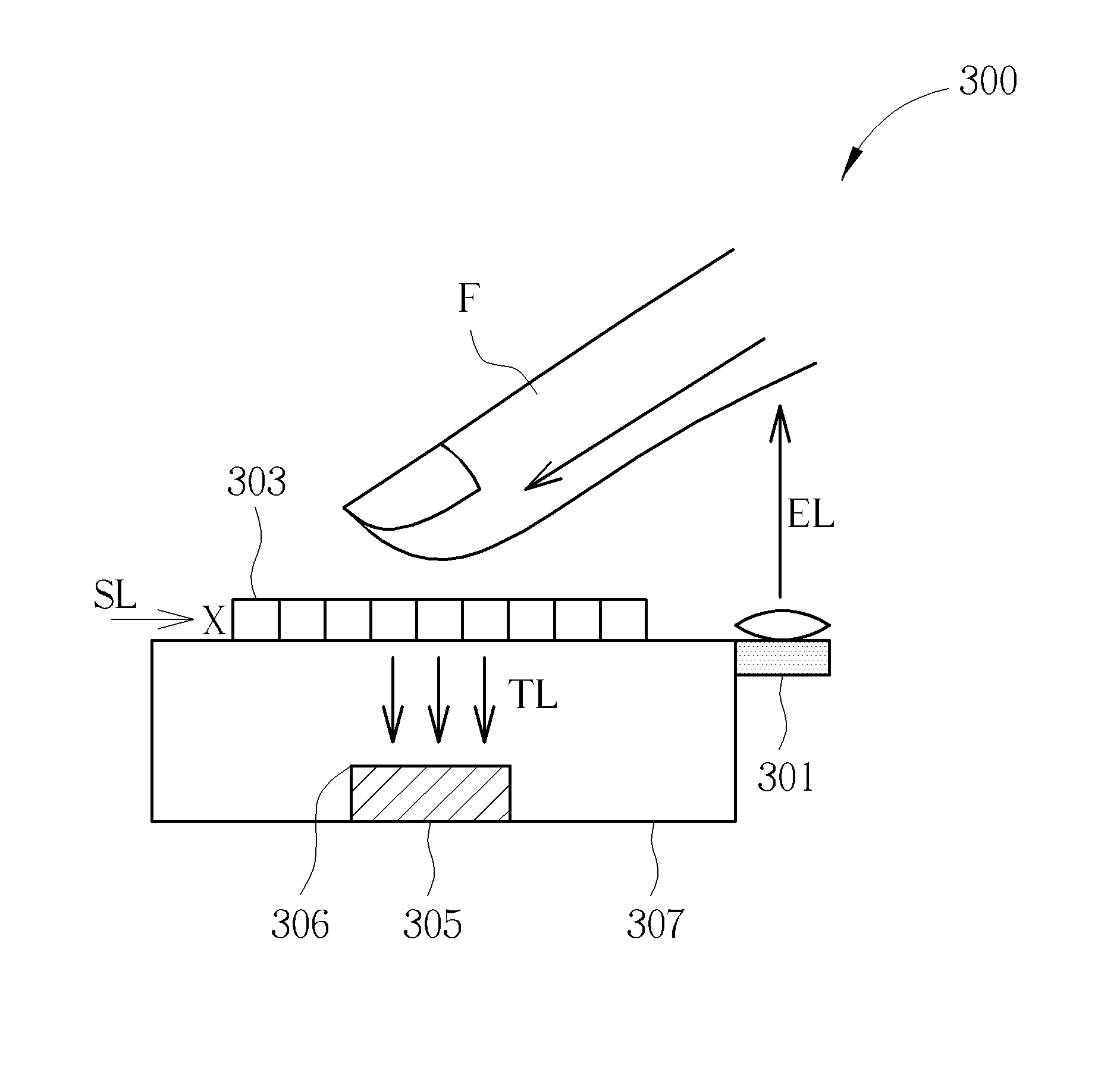
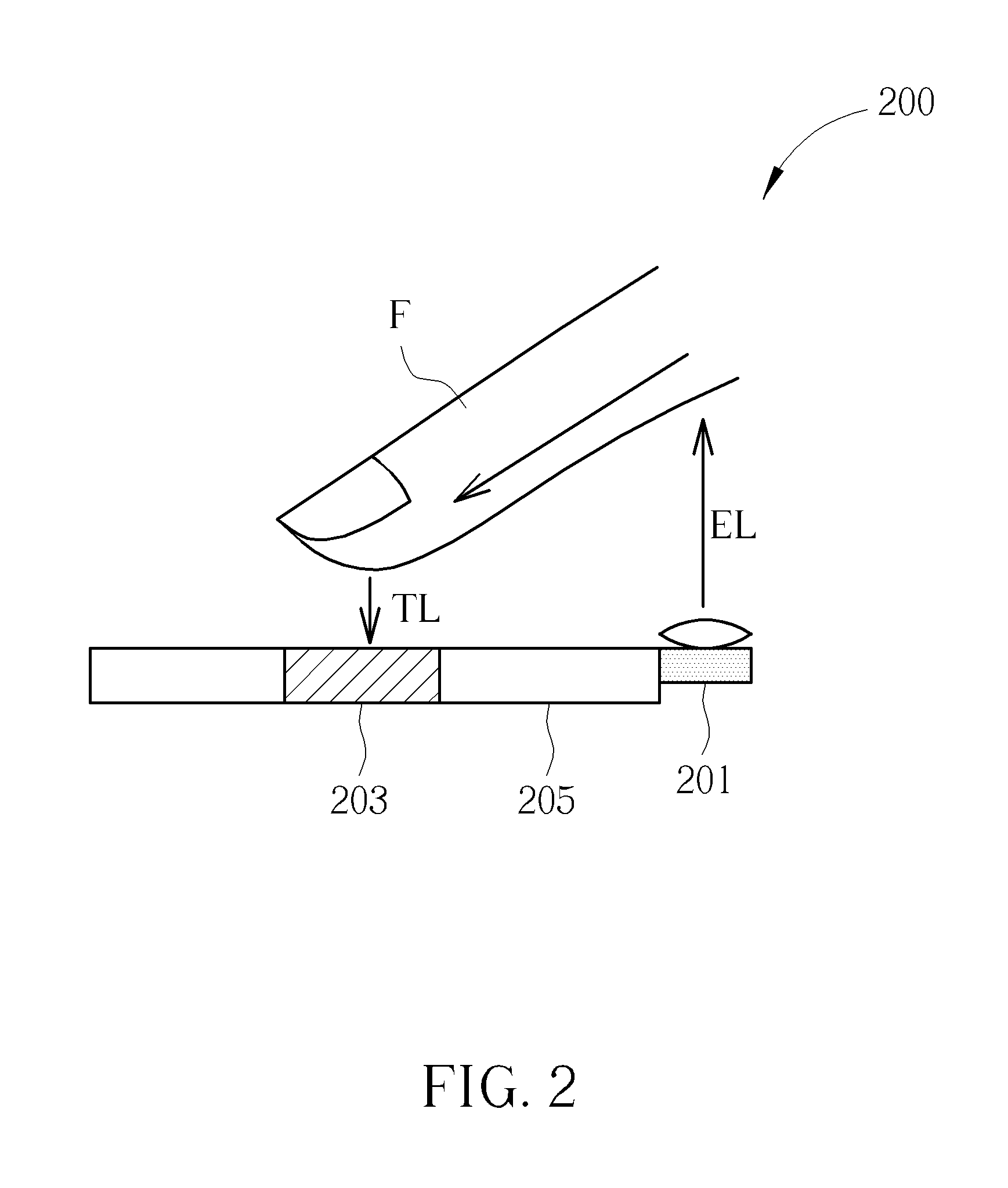
[0018]FIG. 2 to FIG. 5 are schematic diagrams illustrating image capturing apparatuses according to different embodiments of the present invention. As shown in FIG. 2, the image capturing apparatus 200 comprises a light source 201 and a sensor 203. The sensor 203 can be surrounded and protected by protecting material 205 such as epoxy, but is not limited. The light source 201 transmits the incident light EL to an objective, which is a finger F in this embodiment...


PUM

PropertyMeasurementUnit
displacementaaaaaaaaaa
total volumeaaaaaaaaaa
sizeaaaaaaaaaa

Abstract

An image capturing apparatus comprising: a light source, for transmitting incident light to an objective without utilizing any medium besides air, such that the light emits from the objective to generate passing-through light; and a sensor, for capturing an image of the objective according to the passing-through light.

Description

BACKGROUND OF THE INVENTION[0001]1. Field of the Invention[0002]The present invention relates to an image capturing apparatus and an optical displacement estimating apparatus, and particularly relates to an image capturing apparatus and an optical displacement estimating apparatus, which directly emits the light from a light source to a objective without utilizing any medium besides air.[0003]2. Description of the Prior Art[0004]Following the improvement of technique, the touch control apparatus utilizing a machine type touch control device, a capacitor type touch control device or a resistor type touch control device is gradually replaced with an optical touch control apparatus. Such kind of optical touch control apparatus can be regarded as an optical displacement estimating apparatus, since it detects a relative displacement between a objective (ex. a finger) and a detecting surface of the optical displacement estimating apparatus.[0005]Such kind of optical displacement estimatin...

Claims


Application Information

Patent Timeline
Patent Type & Authority Patents(United States)
IPC IPC(8): A61B5/117G01J1/06G01J1/04G01J1/42G01J1/08G01B11/14G01J1/02G06K9/78G06K9/00G01N33/483
CPCG01J1/0204G01B11/14G01J1/0411G01J1/06G01J1/08G01J1/4228G06K9/00033G06K2009/0006G06F3/042G06F2203/0338G06F3/03547G06V40/1341G06V40/1312
Inventor GU, REN-HAUKAO, MING-TSANHUANG, SEN-HUANG
Owner PIXART IMAGING INC
Why Eureka
Try Eureka