Wound drainage therapy system

a therapy system and wound technology, applied in the direction of suction devices, suction drainage containers, intravenous devices, etc., can solve the problems of limited patient stay in hospital, unfavorable patient carrying, and large volume of conventional negative pressure wound care devices

Active Publication Date: 2015-12-01
APEX MEDICAL CORPORATION
View PDF1 Cites 10 Cited by
  • Summary
  • Abstract
  • Description
  • Claims
  • Application Information

AI Technical Summary

Benefits of technology

[0028]Thus, the wound drainage therapy system disclosed herein has modularized parts which can be easily assembled and disassembled with each other, the multiple-pipe integration module of which overcomes the piping entanglement problem, and the fluid collector unit is designed smaller to enable the wound drainage therapy system even more portable.

Problems solved by technology

However, the overall volume of a conventional negative pressure wound care device is too large such that it is not conducive to the patient carries and thus limited to the patients stayed in hospital.
In addition, the conventional negative pressure wound care device is equipped with several pipes such that it is prone to the disadvantage of pipe entanglement that also causes the patients inconvenient.

Method used


Image

  • Wound drainage therapy system
  • Wound drainage therapy system
  • Wound drainage therapy system

Examples


Embodiment Construction

[0042]Reference will now be made in detail to the present preferred embodiments of the invention, examples of which are illustrated in the accompanying drawings. Wherever possible, the same reference numbers are used in the drawings and the description to refer to the same or like parts.

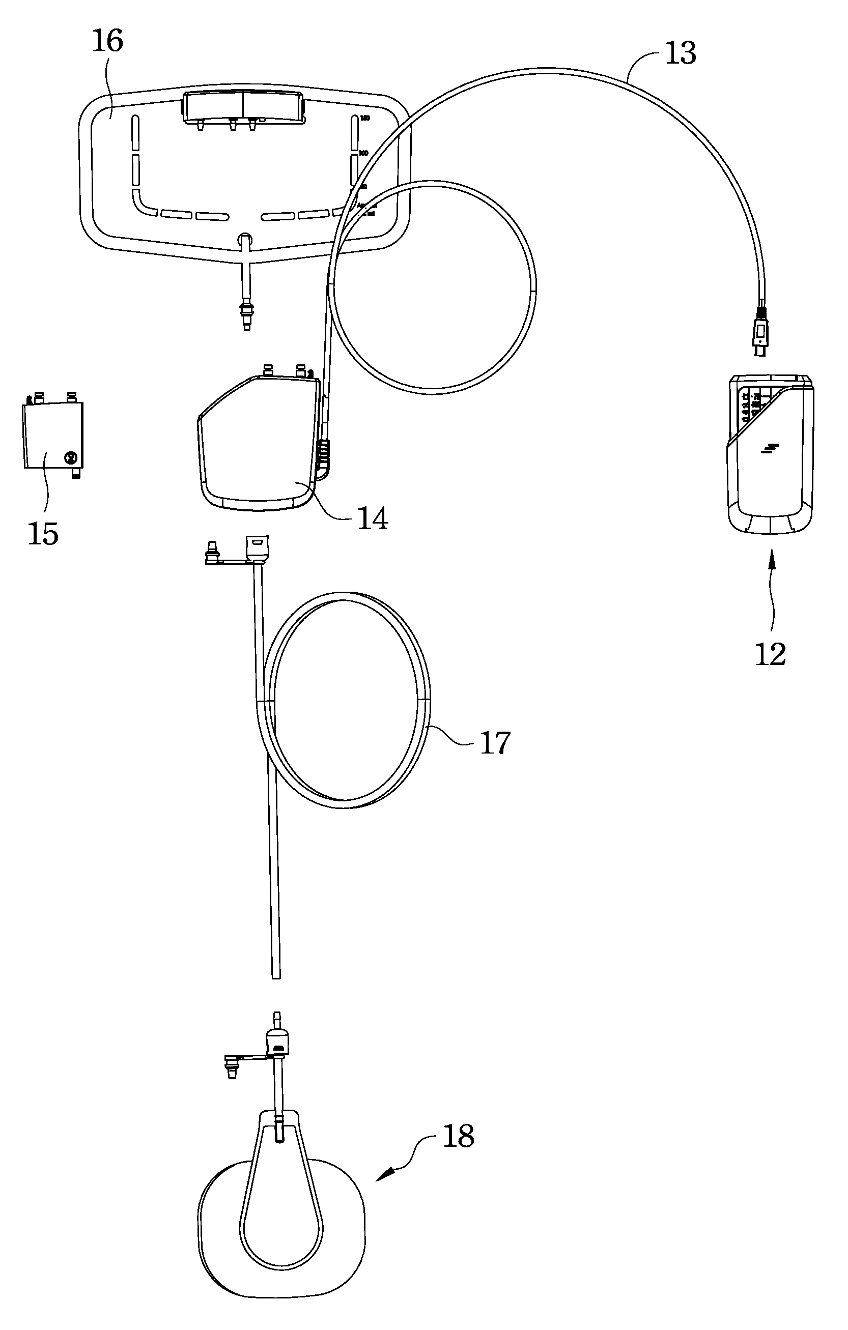
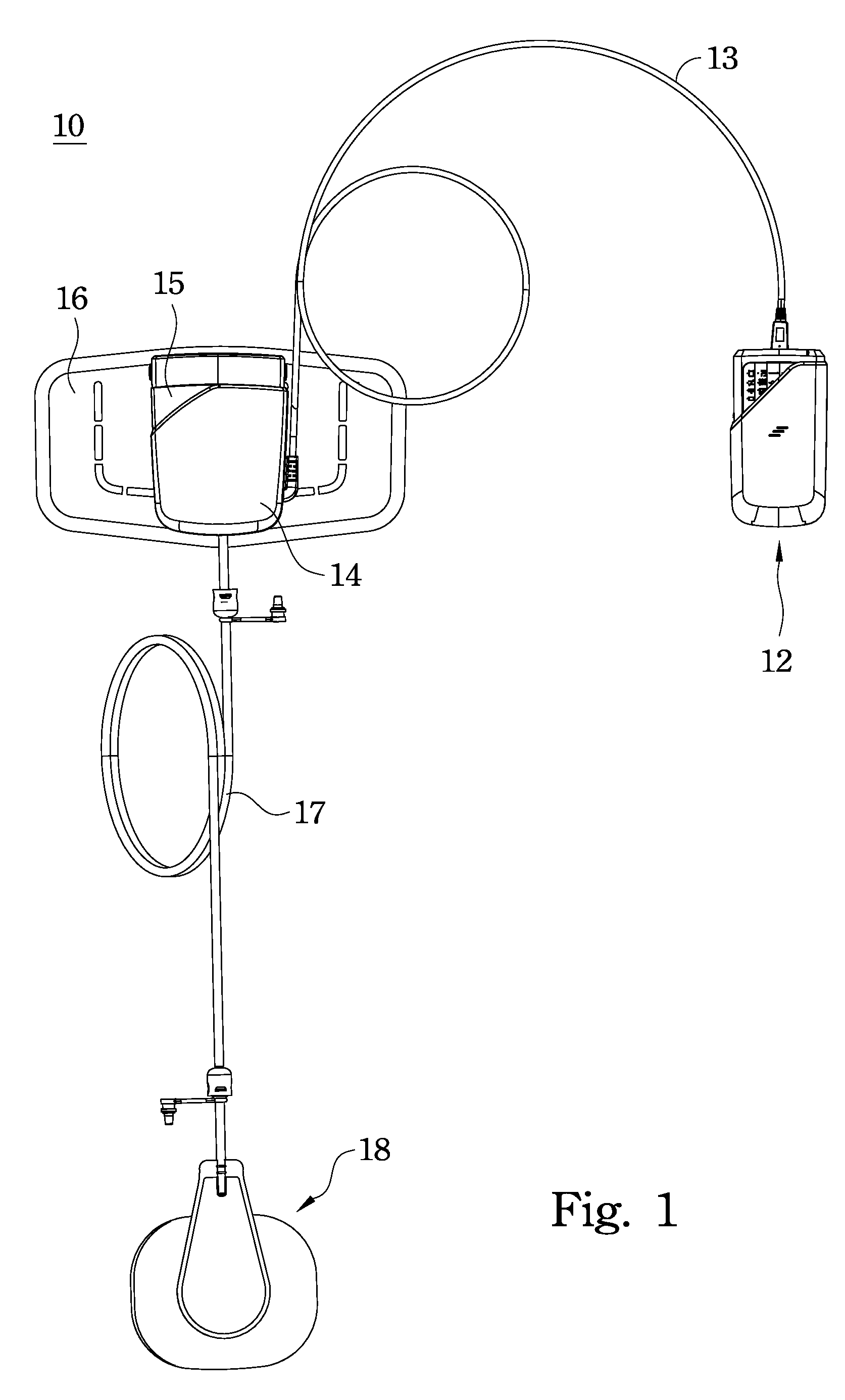
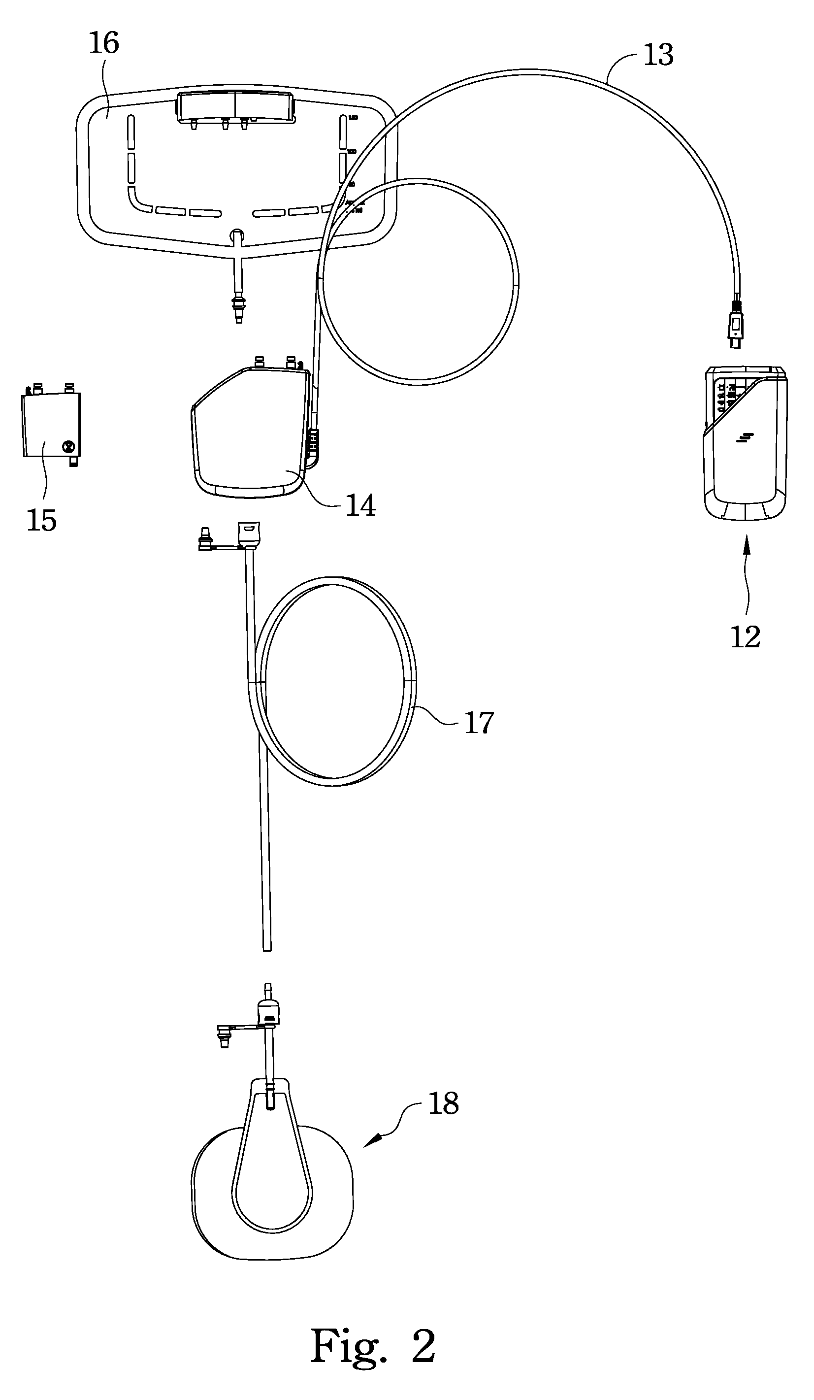
[0043]FIG. 1 illustrates an assembled view of a wound drainage therapy system according to an embodiment of this invention. FIG. 2 illustrates an exploded view of the wound drainage therapy system in FIG. 1. A modularized wound drainage therapy system 10 includes a control unit 12, an actuator 14, a vacuum driving unit 15, a fluid collector unit 16, a connection pipe 17 and a wound seal unit 18, wherein the fluid collector unit 16 and wound seal unit 18 are disposable parts. After the vacuum driving unit 15 is firstly used by a patient, the vacuum driving unit 15 would be infectious and thus should exclusively belong to the patient. The control unit 12 and actuator 14 are electronic parts of the woun...


PUM


Abstract

A wound drainage therapy system includes a wound seal unit, a fluid collector unit, a vacuum driving unit and an actuator. The fluid collector unit is detachably connected with the wound seal unit, and the fluid collector unit has a multiple-pipe integration module and a collection bag. The multiple-pipe integration module has a first row connection port group and a second row connection port group. The vacuum driving unit has a vacuum generator. The actuator has a motor, a negative pressure detector and a positive pressure detector, wherein the motor is used to drive the vacuum generator to operate and the motor is detachably connected with the vacuum generator. A connection port of the negative pressure detector and a connection port of the positive pressure detector are detachably connected with another two connection ports of the second row connection port group respectively.

Description

BACKGROUND[0001]1. Field of Invention[0002]The present invention relates to a wound caring device. More particularly, the present invention relates to a negative pressure wound drainage therapy device.[0003]2. Description of Related Art[0004]Negative pressure wound therapy employs a vacuum pump to provide a negative pressure environment for a wound so as to extract wound pus and infected material, to attract the healthy tissue fluid to maintain a moist healing environment, and to promote the surrounding blood microcirculation, thereby accelerating wound healing effect.[0005]In order to cope with the negative pressure wound therapy, there are a lot of negative pressure wound care devices came into being. However, the overall volume of a conventional negative pressure wound care device is too large such that it is not conducive to the patient carries and thus limited to the patients stayed in hospital. In addition, the conventional negative pressure wound care device is equipped with ...

Claims


Application Information

Patent Timeline
Patent Type & Authority Patents(United States)
IPC IPC(8): A61M1/00
CPCA61M1/0023A61M1/0011A61M1/0088A61M1/0031A61M1/74A61M1/71A61M1/98A61M1/604
Inventor YAO, NAN-KUANGMIAO, LUO-HWAWU, JHY-WENCHIEN, YU-YILI, LI-LINGCHIEN, CHIH-TSAN
Owner APEX MEDICAL CORPORATION
Why Eureka
Try Eureka