Sensor odometry and application in crash avoidance vehicle

a technology of odometry and vehicle, applied in the direction of navigation instruments, using reradiation, instruments, etc., can solve the problems of vehicle dynamics or “dead reckoning” calculations being susceptible to cumulative errors, vehicles not equipped with gps receivers, and sometimes no signal available for equipped gps receivers

Active Publication Date: 2015-12-01
GM GLOBAL TECH OPERATIONS LLC
View PDF13 Cites 34 Cited by
  • Summary
  • Abstract
  • Description
  • Claims
  • Application Information

AI Technical Summary

Benefits of technology

[0006]In accordance with the teachings of the present invention, a method is disclosed for determining an actual trajectory of a vehicle using object detection data and vehicle dynamics data. An object detection system identifies point objects and extended objects in proximity to the vehicle, where the point objects are less than a meter in length and width. An updated vehicle pose is calculated which optimally transposes the point objects in the scan data to a target list of previously-identified point objects. The updated vehicle pose is further refined by iteratively calculating a pose which optimally transposes the extended objects in the scan data to a target model of previously-identified extended objects, where the iteration is used to simultaneously determine a probability coefficient relating the scan data to the target model. The updated vehicle pose is used to identify the actual trajectory of the vehicle, which is compared to a planned path in a collision avoidance system.

Problems solved by technology

However, vehicle dynamics or “dead reckoning” calculations are susceptible to cumulative error.
However, some vehicles are not equipped with GPS receivers, and even vehicle which are equipped with GPS receivers will sometimes have no signal available—such as in tunnels, “urban tunnels” and roads with tall and dense surrounding tree cover.

Method used


Image

  • Sensor odometry and application in crash avoidance vehicle
  • Sensor odometry and application in crash avoidance vehicle
  • Sensor odometry and application in crash avoidance vehicle

Examples


Embodiment Construction

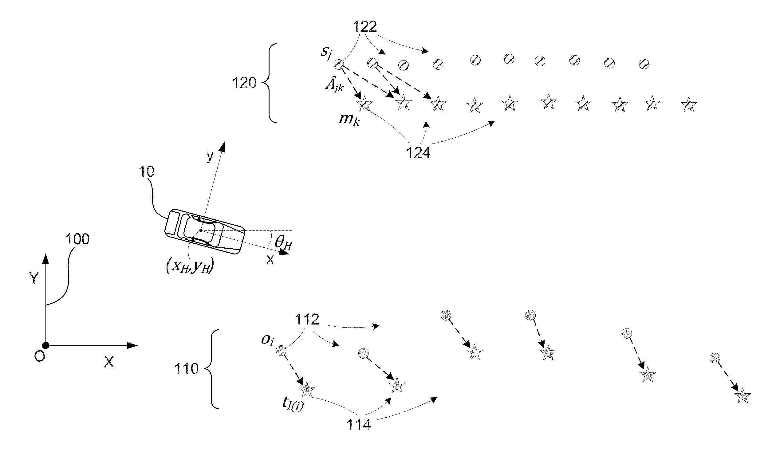
[0012]The following discussion of the embodiments of the invention directed to a method for determining an actual trajectory of a vehicle using object detection data and vehicle dynamics data is merely exemplary in nature, and is in no way intended to limit the invention or its applications or uses.

[0013]Some vehicles are now equipped with collision avoidance systems which can take control of vehicle steering and braking in situations where a vehicle collision appears to be imminent. Collision avoidance systems determine a desired path for the vehicle to take in order to avoid the collision, measure actual vehicle trajectory, and make steering / braking corrections in real time. Actual vehicle trajectory is typically determined in these systems using a combination of vehicle dynamics data and GPS data. However, in vehicles which are not equipped with a GPS receiver, and in situations where GPS data is not available due to sky visibility obstructions, another source of vehicle position...


PUM


Abstract

A method for determining an actual trajectory of a vehicle using object detection data and vehicle dynamics data. An object detection system identifies point objects and extended objects in proximity to the vehicle, where the point objects are less than a meter in length and width. An updated vehicle pose is calculated which optimally transposes the point objects in the scan data to a target list of previously-identified point objects. The updated vehicle pose is further refined by iteratively calculating a pose which optimally transposes the extended objects in the scan data to a target model of previously-identified extended objects, where the iteration is used to simultaneously determine a probability coefficient relating the scan data to the target model. The updated vehicle pose is used to identify the actual trajectory of the vehicle, which is compared to a planned path in a collision avoidance system.

Description

BACKGROUND OF THE INVENTION[0001]1. Field of the Invention[0002]This invention relates generally to enhanced trajectory tracking of an automobile and, more particularly, to a method for relative positioning of a host vehicle with respect to surrounding static obstacles and moving targets which uses object detection data along with vehicle dynamics data to compute a closed loop trajectory of the host vehicle, and uses the trajectory in path planning for collision avoidance or other purposes.[0003]2. Discussion of the Related Art[0004]Many vehicles now include systems which can actively control the path of the vehicle—for applications such as collision avoidance. These systems, when they detect a need to alter the path of the vehicle, will determine a desired new path for the vehicle to follow, implement braking and / or steering commands to achieve the desired path, monitor the actual trajectory of the vehicle relative to the desired path, and make further corrections to follow the des...

Claims


Application Information

Patent Timeline
Patent Type & Authority Patents(United States)
IPC IPC(8): G06F17/10B60W30/095
CPCB60W30/0953B60W2420/52B60W2550/10G01C21/3446B60W40/10B60W2554/00G01S7/415G01S13/726G01S13/931G01S2013/932G01S2013/9322G01S2013/9323G01S2013/93271
Inventor ZENG, SHUQING
Owner GM GLOBAL TECH OPERATIONS LLC
Why Eureka
Try Eureka