Method and device for shading in a display system

a display system and display device technology, applied in the direction of identification means, lighting and heating apparatus, instruments, etc., can solve the problems of difficult manufacturing, difficult to remove if any repair work needs to be done to leds or led pcbs, and the shading device must be firmly connected

Active Publication Date: 2015-12-01
BARCO NV
View PDF8 Cites 6 Cited by
  • Summary
  • Abstract
  • Description
  • Claims
  • Application Information

AI Technical Summary

Benefits of technology

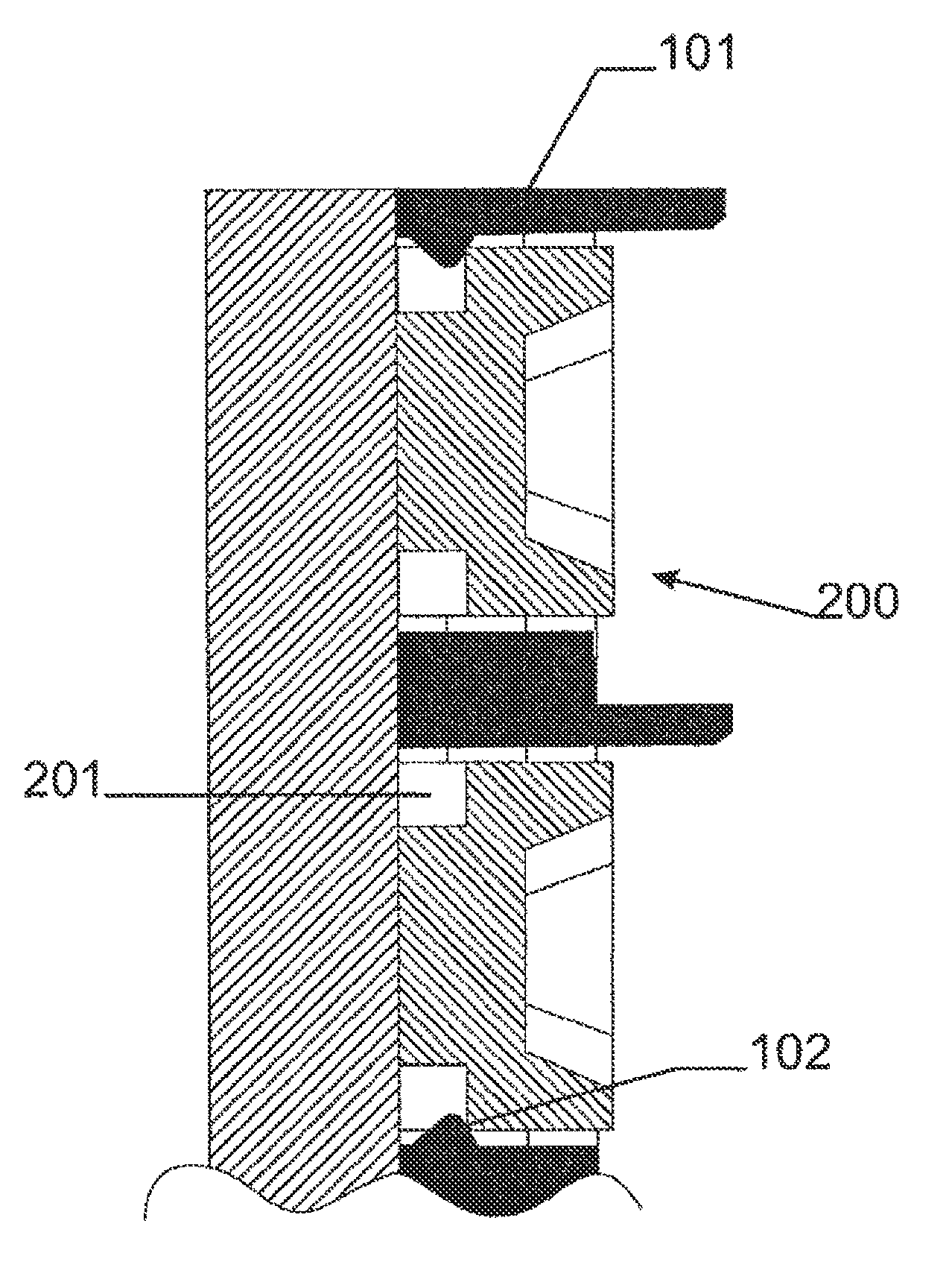
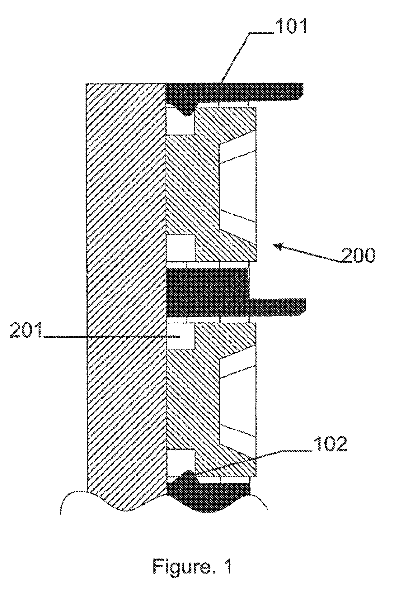
[0005]It is an object of the present invention to provide good shading devices, display systems for use with such shading devices and methods for installing shading devices on display systems. It is an advantage of some embodiments of the present invention that a method is provided by which a shading device, e.g. comprising a number of shader elements or louvers, may be mechanically connected to a display system, e.g. a LED PCB of a LED display, by a plurality of soft connections instead of a few hard connections. It is an advantage of embodiments of the present invention that soft connections may be established by mechanically locking the shading device, e.g. shader structure, to the display system, e.g. LED package. Because of the omnipresence of the LEDs lots of these connections can be made.
[0008]It is furthermore an advantage of embodiments of the present invention that by providing simple mechanical provisions or fixing means to the shader, the shader can simply click onto the LED package. By making it a soft click, the mechanical fix per light source unit, e.g. LED package, may be weak, in a way that damage or hard pulling to the light source unit, e.g. LED package, is avoided.
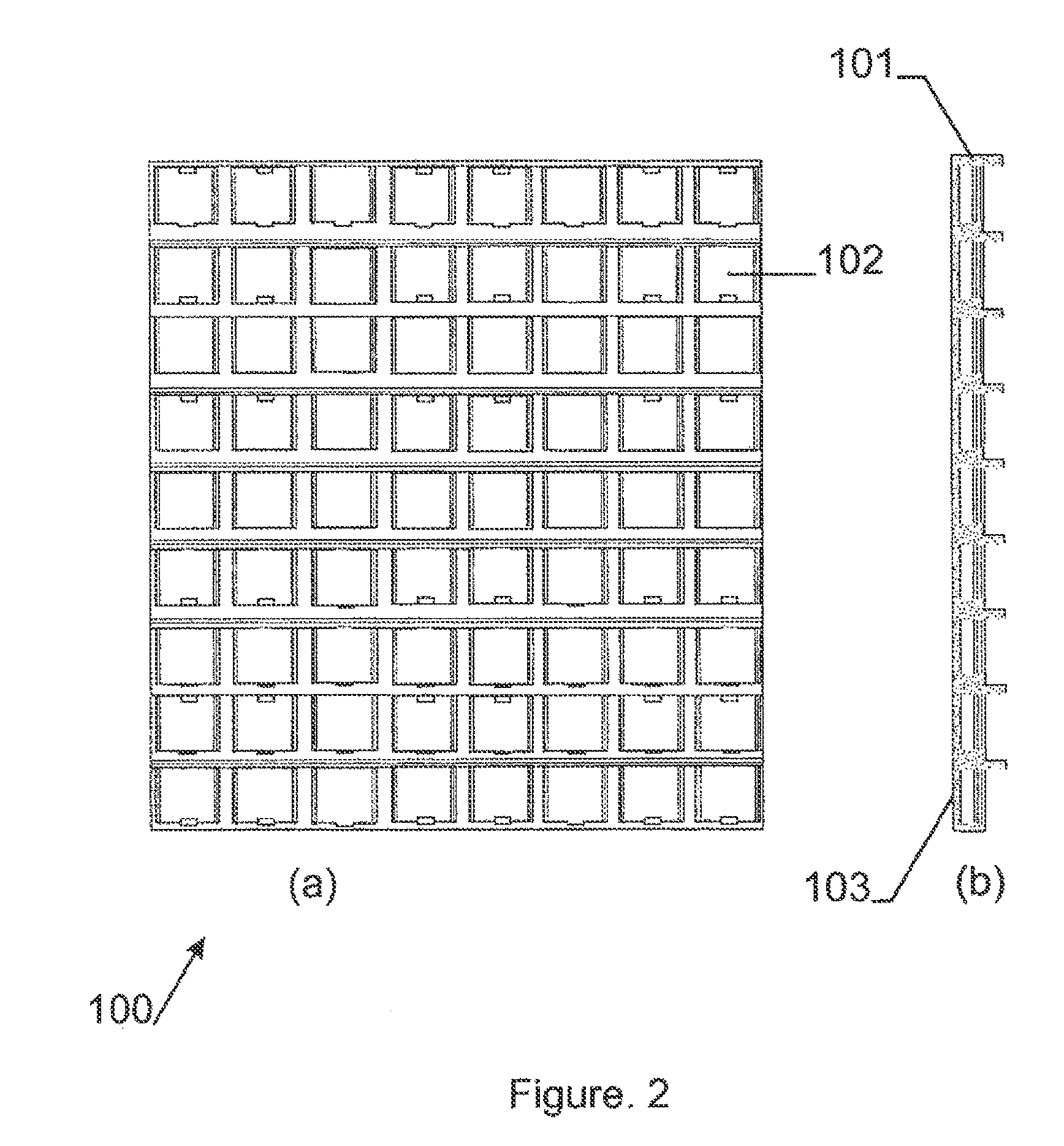
[0009]It is an advantage of embodiments of the present invention that, by providing a plurality of connections, e.g. lots of weak mechanical connections, distributed evenly over the display system viewing plane, e.g. distributed evenly over the LED PCB, a multitude of mechanical soft fixes can be achieved, yielding a firm shader fix. The shading device may completely follow and match onto the underlying surface. The shading device fixation design can be very simple, because only simple fixing means, e.g. mechanical fixing means, need to be provided in the structure of the shading device. It is also an advantage of embodiments of the present invention that the shading device can easily be removed and re-applied.
[0010]It is an advantage of embodiments according to the present invention that the fixing of the shading device to the display system can be firm.
[0011]It is an advantage of embodiments according to the present invention that the fixing elements may be connected to the display system at a plurality of points to the display system, e.g. substantially uniformly spread over the display system resulting in a uniform fixing to the display system. The load on the display system in this way may be spread over the display system, resulting in little or no deformation forces from the shading device on the display, system.

Problems solved by technology

One of the main problems with shaders is the way to attach them to the LED printed circuit board (PCB).
Usually the shader is glued to the LED PCB, leading to difficulty to remove if any repair work needs to be done to the LEDs or the LED PCB.
A removable shading device is convenient however very difficult to manufacture.
Major problem is that the shading device must be firmly connected to the front of the LED PCB.
These clips are very vulnerable to breaking and moreover with very small pitch (e.g. 4 mm) clips are almost impossible to add to the shader mechanics.
Because of the difficulty to add clips, only a few of them are usually added which results in very bad and irregular mechanical fitting of the shading device to the LED PCB.
This irregular fitting results in uneven mechanical fitting of the shader, overall on the front of the display, which finally causes a non uniform display.

Method used


Image

  • Method and device for shading in a display system
  • Method and device for shading in a display system
  • Method and device for shading in a display system

Examples


Embodiment Construction

[0018]The characteristics, features and advantages of the present invention will become apparent from the following description, taken in conjunction with the accompanying drawings, which illustrate, by way of example only, the principles of the invention. This description is given for the sake of example only, without limiting the scope of the invention. The reference figures quoted below refer to the attached drawings.

[0019]It is to be noticed that the term “comprising”, used in the claims, should not be interpreted as being restricted to the means listed thereafter; it does not exclude other elements or steps. It is thus to be interpreted as specifying the presence of the stated features, integers, steps or components as referred to, but does not preclude the presence or addition of one or more other features, integers, steps or components, or groups thereof. Thus, the scope of the expression “a device comprising means A and B” should not be limited to devices consisting only of ...


PUM


Abstract

The present invention relates to a shading device for use with a display system. The shading device comprising fixing means (102) for fixing onto the display system.

Description

TECHNICAL FIELD OF THE INVENTION[0001]The present invention relates to systems, devices and methods for displaying information. More particularly, the present invention relates to systems, devices and methods for shading in display systems, and to display systems or devices using such shading systems.BACKGROUND OF THE INVENTION[0002]Modern light emitting diode (LED) displays increasingly use optical systems at the front of the display in order to increase optical performance characteristics, such as contrast ratio, brightness, viewing angle, colour compound.[0003]One of the most frequently used devices for increased optical performance, is the shading device. A shader for LED displays generally consists of a grid which fits over the LEDs and fills up the space between the LEDs. The shading device can have several optical features like louvers for avoidance of angled direct light hitting the front of the LED. Other optical features embedded in the shading device are light-traps which...

Claims


Application Information

Patent Timeline
Patent Type & Authority Patents(United States)
IPC IPC(8): F21V1/00G09F9/33F21V7/00G09F13/22F21Y105/00
CPCG09F9/33G09F13/22F21V7/0083F21Y2105/001F21Y2105/10F21Y2115/10
Inventor MEERSMAN, KARIM
Owner BARCO NV
Why Eureka
Try Eureka