Method for manufacturing a housing element having a decorative covering and a grip layer

a housing element and decorative technology, applied in the field of manufacturing a housing element having a decorative covering and a grip layer, can solve the problems of shaver falling on the ground, less appealing to consumers, damaged shaver, etc., and achieves good adhesion, prevents washout of printing ink, and good adhesion of the grip layer

Active Publication Date: 2015-12-08
KONINK PHILIPS ELECTRONICS NV
View PDF32 Cites 0 Cited by
  • Summary
  • Abstract
  • Description
  • Claims
  • Application Information

AI Technical Summary

Benefits of technology

[0011]According to the present invention, a foil having a decorated side is used for realizing a decorated appearance of the element, wherein a grip layer is applied to the decorated side of the foil. In this way, the soft-touch grip section of the element is formed. Within the scope of the present invention, the material of the grip section may be translucent, so that the decoration may be visible through the grip section. Besides the grip layer, which is applied to the decorated side of the foil, another layer is provided, namely a supportive layer, which is applied to another side of the foil. On the basis of this supportive layer, the element obtains a required stiffness and robustness. Preferably, the material for forming the supportive layer is processed at a temperature above 295° C., for instance at a temperature of 300° C., so that sufficient adhesion of the supportive layer to the foil may be realized.
[0013]Advantageously, a material having a hardness of lower than 70 Shore A, in a solidified state, is used as the second material for forming the grip layer. In that way, it is ensured that a sufficient grip effect is realized. Furthermore, forming the grip layer with interruptions according to a predetermined pattern contributes to the grip effect. For example, the pattern of interruptions may be chosen such that a rib structure is obtained in the grip layer.
[0018]When the method according to the present invention is applied for the purpose of manufacturing an element, it is very well possible to obtain both a good adhesion of the layers to the foil and to avoid deterioration of the decoration, even in case of an element having special features which are known such as to have a decreasing effect on the adhesion and / or an increasing effect on the washout of printing ink. In this respect, it is noted that in general, it is more difficult to guarantee a sufficient extent of adhesion and an unaffected decoration in situations in which a metallic surface effect is wanted, an extremely curved shape is wanted, a translucent material is used for forming the grip layer, a material having a hardness of lower than 70 Shore A is used for forming the grip layer, a high chemical resistance is wanted and / or it is desired to make the grip layer with thin rubber strips having a small wall thickness.
[0024]The decorative covering of the foil comprises one or more color layers of coloring material, wherein an activation temperature of this material is relatively high, for example above 260° C., whereas the activation temperature of the material of the adhesive layer is relatively low, for example below 200° C. When the foil is applied in a process of manufacturing an element having a decorative look and a soft-touch grip section, a grip layer of relatively soft material is applied on top of the adhesive layer. Due to the different activation temperatures of the materials of the decorative covering and the adhesive layer of the foil, it is very well possible to process the material of the grip layer at a temperature for guaranteeing a good adhesion to the adhesive layer of the foil on the one hand, and for preventing washout of printing ink of the decorative covering on the other hand. For example, the processing temperature may be close to 200° C. For sake of completeness, it is noted that a good adhesion of the grip layer to the adhesive layer of the foil is very important, as situations in which the grip layer may easily be peeled off of the adhesive layer need to be avoided, particularly in case the element comprising the foil and the grip layer is applied in a consumer product.
[0025]The at least one color layer of the decorative covering of the foil may be formed with at least one interruption. In this way, it is possible to create one or more windows in the color layer. A special optical effect may be obtained when the decorative covering comprises several color layers, and when one of the color layers, which is covered by at least one other color layer, is provided with at least one interruption. When the foil is part of an element having a grip layer comprising translucent material, wherein the element is a housing element that is positioned at an outer side of a product having an internal light source, the at least one window in the foil allows the light to pass, wherein the light is scattered by the top color layer(s) and the grip layer.
[0026]Within the scope of the present invention, many ways of obtaining interesting optical effects are feasible. For example, the decorative covering may comprise a semitransparent vacuum metallized layer for realizing a metallic surface effect.

Problems solved by technology

Hand-held appliances such as mobile phones, audio equipment and personal care products are getting smaller due to miniaturization of components.
In case it is desired to provide an appliance with a soft-touch grip section for realizing a grip effect, there is only little space for a decorative section, as a result of which the appliance is less appealing to consumers.
In many cases, in order to prevent a user of the shaver from losing grip on the shaver, which may even lead to a situation in which the shaver falls on the ground and gets damaged, a section of the shaver is covered by a rubber-like material.
However, it is not possible to cover the whole surface of the soft-touch grip section, especially when this section and the surface have a curved shape.

Method used


Image

  • Method for manufacturing a housing element having a decorative covering and a grip layer
  • Method for manufacturing a housing element having a decorative covering and a grip layer
  • Method for manufacturing a housing element having a decorative covering and a grip layer

Examples


Embodiment Construction

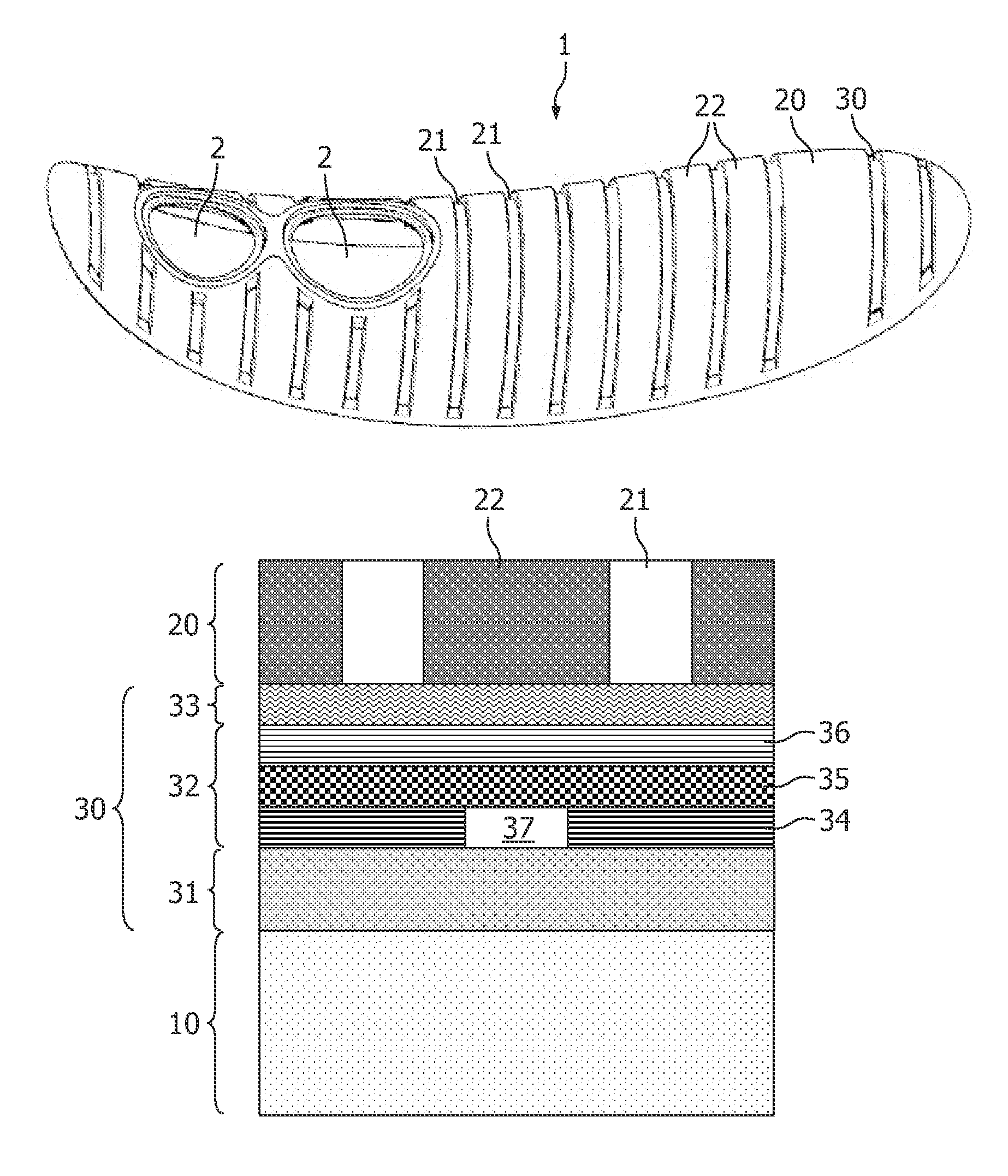
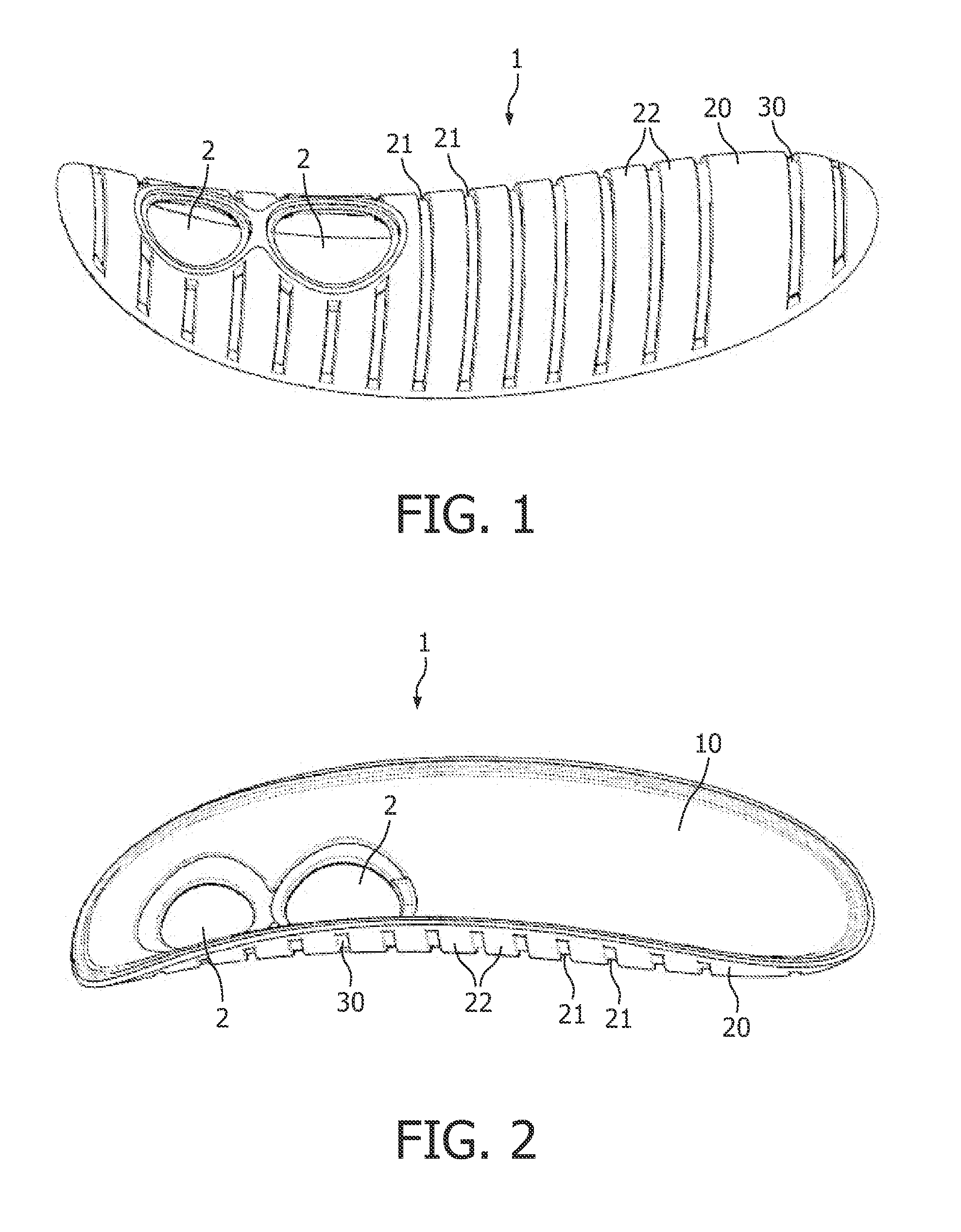
[0039]FIGS. 1 and 2 show a housing element 1 which is intended to be used in a shaver. In particular, the housing element 1 is intended to be part of a grip portion of a shaver, i.e. a portion of the shaver which is taken hold of by a user when the user wants to perform a shaving action by means of the shaver. In FIG. 1, the housing element 1 is shown with an outer side up, whereas in FIG. 2, the housing element 1 is shown with an inner side up.

[0040]In the shown example, the housing element 1 has two holes 2. The number of holes 2 is not essential within the scope of the present invention, and the holes 2 may be omitted altogether. The holes 2 may serve for accommodating a button or the like for operating the shaver, or for providing an unhindered view to a display, for example.

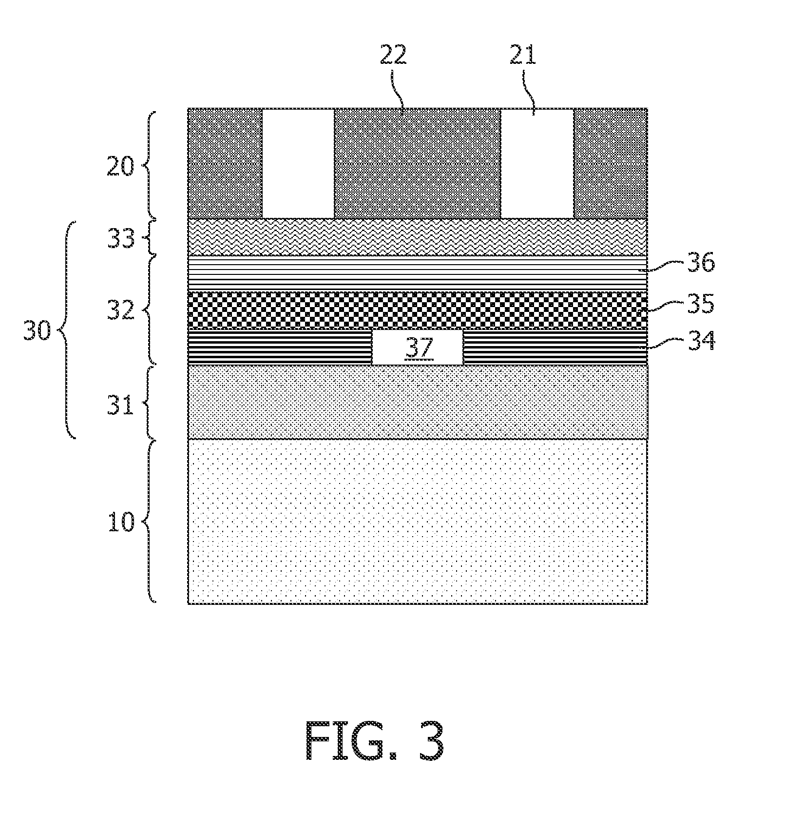
[0041]The housing element 1 has a layered structure, wherein the layers are firmly interconnected. In particular, the housing element 1 comprises a supportive layer 10 of a relatively hard material, a grip l...


PUM

PropertyMeasurementUnit
temperatureaaaaaaaaaa

Abstract

A housing element of a product includes a foil having a decorated side, where this decorated side of the foil is covered by a grip layer for realizing a grip effect. The other side of the foil is covered by a supportive layer. The grip layer may have a rib structure. Each of the supportive layer and the grip layer is applied to the foil in an injection molding process. A processing temperature of the material of the grip layer is significantly lower than an activation temperature of printing ink of a decorative covering of the foil, so that washout of the printing ink is prevented. Further, material of an adhesive layer of the foil is configured to establish adhesion to the material of the grip layer at this relatively low temperature.

Description

FIELD OF THE INVENTION[0001]The present invention relates to a method for manufacturing an element which is intended to be applied as a part of a product such as a product for domestic appliance or a personal care product, in particular an element having a soft-touch grip section for realizing a grip effect, so that a user of the product having the element may have a firmer grip on the product than in case the grip section would be absent.[0002]The present invention also relates to a method for manufacturing a product such as a product for domestic appliance or a personal care product, comprising a step of manufacturing a housing element of the product, which involves carrying out the above-described method for manufacturing an element.BACKGROUND OF THE INVENTION[0003]Hand-held appliances such as mobile phones, audio equipment and personal care products are getting smaller due to miniaturization of components. At the same time, there is a need for a nicely decorated appearance of th...

Claims


Application Information

Patent Timeline
Patent Type & Authority Patents(United States)
IPC IPC(8): B29C45/16B29C45/14
CPCB29C45/1671B29C45/14811B29C45/14688B29C45/1676B29K2715/006B29K2995/002Y10T428/24479Y10T428/24983Y10T428/2804
Inventor PETZ, HUBERTVUGTS, MARINUS ARNOLDUS MARTINUSBLEEKER, MICHELOPZEELAND, JOHANNES BERNARDUS VALENTINUS VANMULDER, GEERTBODEWITS, ERWIN
Owner KONINK PHILIPS ELECTRONICS NV
Why Eureka
Try Eureka