
Electromagnetic marine fender

a technology of electromagnetic marine fender and fender body, which is applied in the direction of magnets, magnets, vessel construction, etc., can solve the problems of poor safety, easy damage to mooring cables and cable guide holes, and limited methods, etc., and achieves complicated operations, high requirements, and poor safety.

Inactive Publication Date: 2015-12-08
DALIAN UNIV OF TECH
View PDF4 Cites 0 Cited by
  • Summary
  • Abstract
  • Description
  • Claims
  • Application Information

AI Technical Summary

Benefits of technology

The electromagnetic marine fender system enhances safety and stability during ship-ship berthing by providing a secure magnetic attraction force, reducing hull damage and operational complexities, and can be used in various sea conditions and ship types.

Problems solved by technology

However, such a method is restricted by many factors and has poor security.
First, when the height difference between the decks of the two ships and the water level is too large, the mooring cables and the cable guide holes are easily damaged, and transverse movements still exist after the mooring.
In addition, under the action of periodical dynamic load, the two ships may collide with each other.
Second, the mooring device is restricted by the longitudinal positions of the cable guide holes.
When the space between the longitudinal positions of one pair of the cable guide holes of two ships is too large, the pulling force of the cable is primarily exerted on the cable guide holes, thus resulting in loose anchoring.
In case of relatively large waves, the transverse rotation of the two ships often causes collisions between the upper constructions and the masts, which is very dangerous.

Method used


Image

  • Electromagnetic marine fender
  • Electromagnetic marine fender
  • Electromagnetic marine fender

Examples


Embodiment Construction

[0024]For further illustrating the invention, experiments detailing an electromagnet marine fender are described below. It should be noted that the following examples are intended to describe and not to limit the invention.

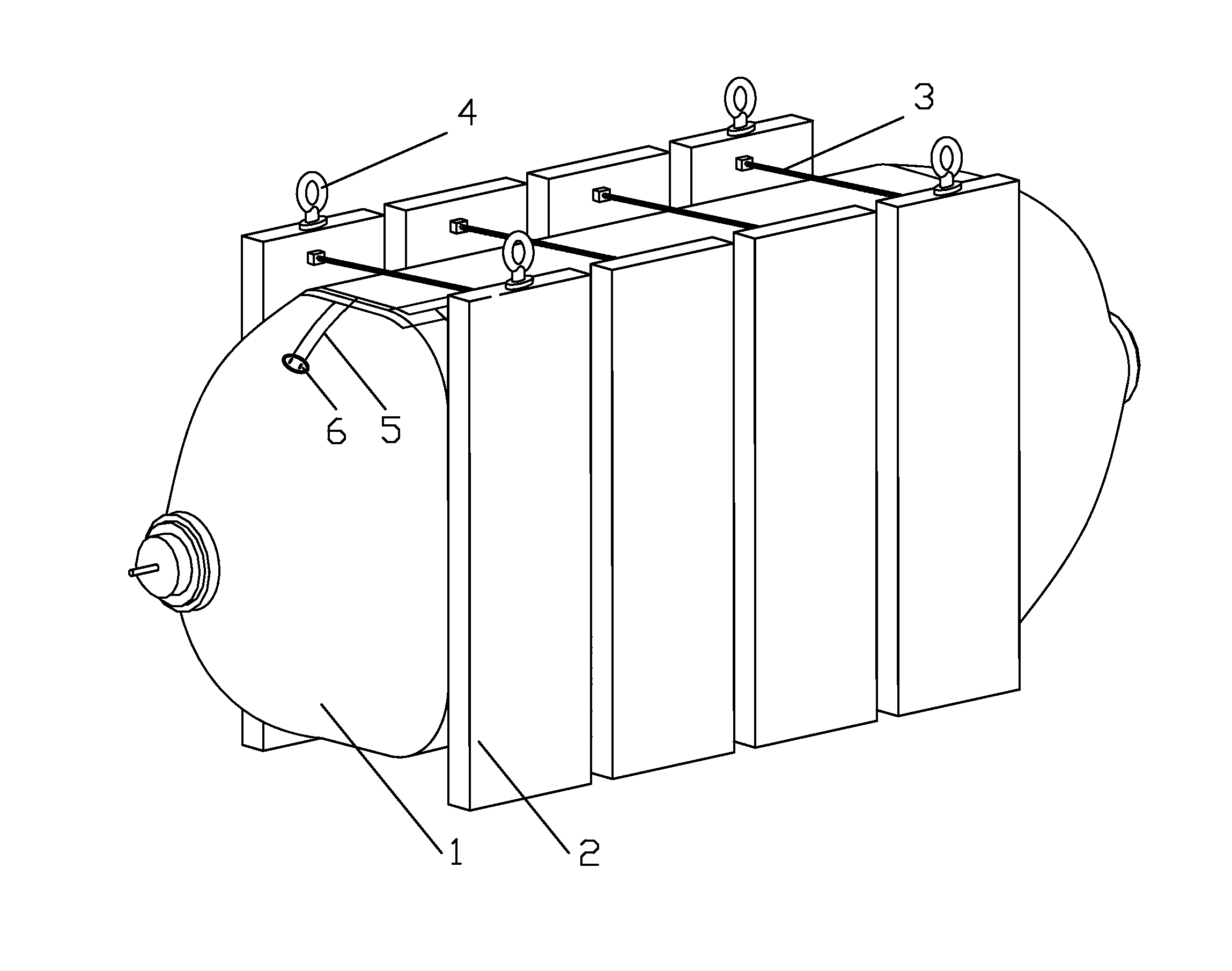
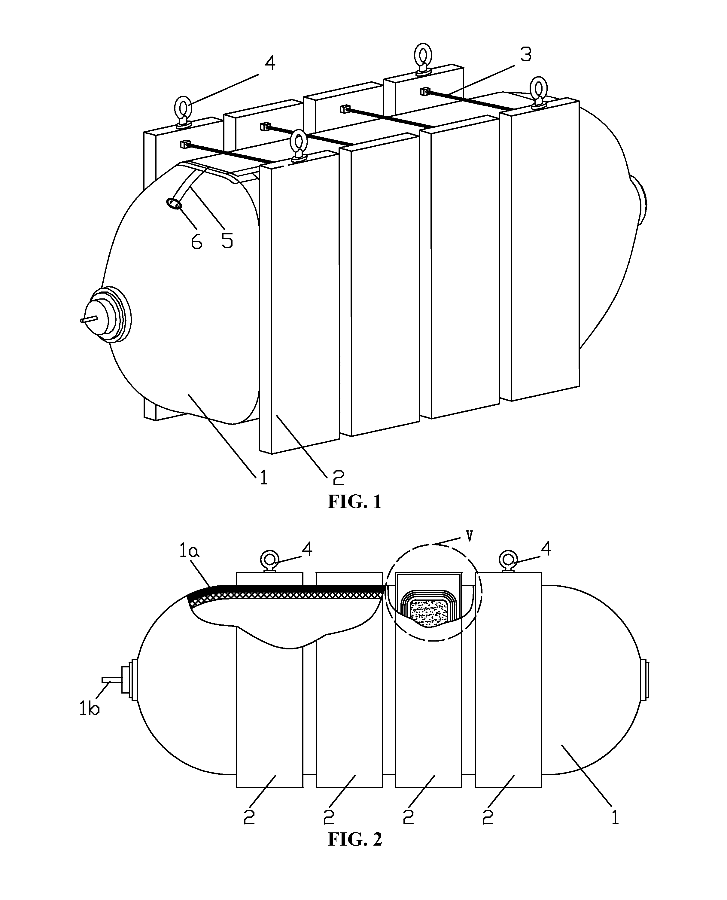
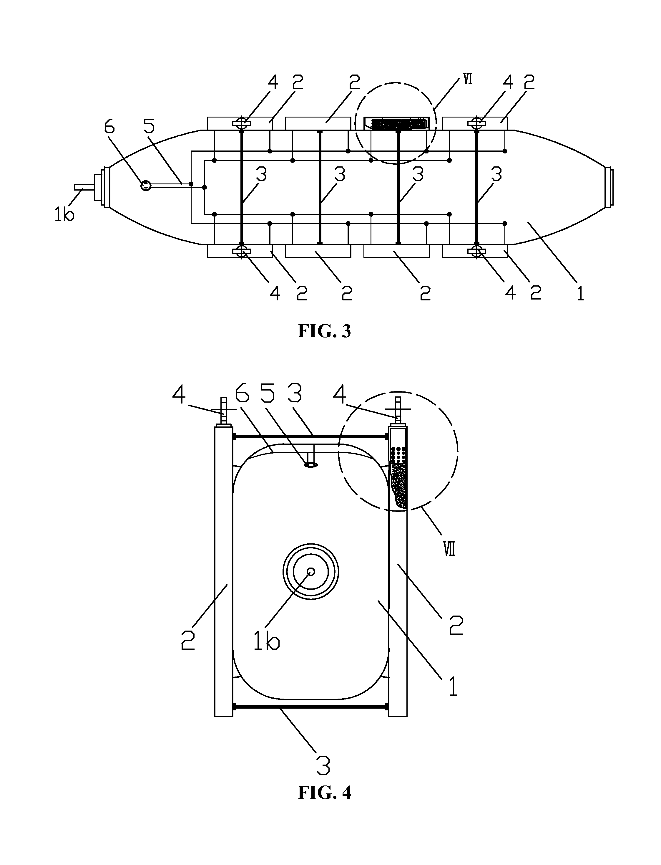
[0025]Overall structures of an electromagnet marine fender are illustrated in FIGS. 1-7. The electromagnet marine fender comprises a rubber fender 1 and two electromagnet groups. Each electromagnet group adopts four magnets comprising coils winded in the same direction. The electromagnet groups are disposed on two sides of the rubber fender 1. The rubber fender 1 and the electromagnet groups arranged on the two sides thereof are fixed and connected together as a whole by tensile steel ropes 3. The electromagnet 2 is a combination structure comprising an electromagnet core 2b, an electromagnet coil 2a, an electromagnet steel shell 2c, and a rubber coating 2d covering the electromagnet steel shell 2c from the center outward. When the electromagnet coils 2a of all th...


PUM

PropertyMeasurementUnit
magnetic forceaaaaaaaaaa
heightaaaaaaaaaa
pulling forceaaaaaaaaaa

Abstract

An electromagnetic marine fender, including: a rubber fender, two electromagnet groups, tensile steel ropes, an electric cable, and a waterproof power socket. Each electromagnet group includes at least one electromagnet. The electromagnet coils of the electromagnets have the same winding direction. The two electromagnet groups are disposed on two sides of the rubber fender, and the two electromagnet groups and the rubber fender are connected and fixed as a whole by the tensile steel ropes. The electromagnet is a combination structure including an electromagnet core, an electromagnet coil, an electromagnet steel shell, and a rubber coating covering the electromagnet steel shell from the center outward. The electromagnet coils of the electromagnets of the two electromagnet groups are connected in parallel, and the two electromagnet groups are in electric connection to the waterproof power socket via the electric cable.

Description

CROSS-REFERENCE TO RELATED APPLICATIONS[0001]This application is a continuation-in-part of International Patent Application No. PCT / CN2014 / 000379 with an international filing date of Apr. 8, 2014, designating the United States, now pending, and further claims priority benefits to Chinese Patent Application No. 201310155374.6 filed May 2, 2013. The contents of all of the aforementioned applications, including any intervening amendments thereto, are incorporated herein by reference. Inquiries from the public to applicants or assignees concerning this document or the related applications should be directed to: Matthias Scholl P. C., Attn.: Dr. Matthias Scholl Esq., 245 First Street, 18th Floor, Cambridge, Mass. 02142.BACKGROUND OF THE INVENTION[0002]1. Field of the Invention[0003]The invention relates to an electromagnetic marine fender.[0004]2. Description of the Related Art[0005]A typical method for ship-ship berthing at sea is mooring one ship to another. However, such a method is r...

Claims


Application Information

Patent Timeline
Patent Type & Authority Patents(United States)
IPC IPC(8): B63B59/02H01F7/20H01F7/06
CPCB63B59/02H01F7/202B63B2059/025B63B2231/30H01F2007/062B63B21/02H01F7/206
Inventor YU, YANYUNLIN, YANCHEN, MINGWANG, YUNLONGLI, KAI
Owner DALIAN UNIV OF TECH
Learn More