
System and method for submerging a hydraulic turbine engine

Inactive Publication Date: 2012-04-05
ELECTRICITE DE FRANCE +1
View PDF7 Cites 3 Cited by
  • Summary
  • Abstract
  • Description
  • Claims
  • Application Information

AI Technical Summary

Benefits of technology

[0013]An object of an embodiment of the present invention is to provide a fast and safe installation, which does not require the presence of divers or of large crafts.
[0014]An object of an embodiment of the present invention is to provide an installation which can use current non-specific vessels.

Problems solved by technology

Second, limiting the machine installation cost is essential.
Now, in many currently-used systems, this cost may largely exceed machine manufacturing costs.
The drilling or piling operations necessary to install the piles are hazardous and technically long, difficult, and expensive since they are the transposition of complex operations used for offshore oil drilling.
Further, such foundations are heavy and bulky.
Lastly, operations are risky on high seas if the vessel does not itself have considerable dimensions to remain steady in the swell during transshipment operations.
But they have a low availability and bring about very high operating costs (handling, transport).
Thus solution has several disadvantages:it requires a dedicated floating platform;in the case where the platform is towed (less expensive option preferred by the authors), the maneuverability of the platform+tug assembly is low and makes it difficult to face harsh weather conditions during the travel from the port of departure to the selected site or from the port of departure to another portion of departure (this last operation requires, according to authors, the dismantling of the platform and its transportation in a cargo ship);the pre-installation alongside the quay of the port of departure is not direct;during the laying down, reaching given positioning parameters of the turbine engine+base assembly is either difficult (orientation of the turbine engine with respect to the current via a management of several pull lines fastened to the foundation), or impossible (the horizontality of the turbine engine cannot be provided if the bottom is not horizontal).

Method used


Image

  • System and method for submerging a hydraulic turbine engine
  • System and method for submerging a hydraulic turbine engine
  • System and method for submerging a hydraulic turbine engine

Examples


Embodiment Construction

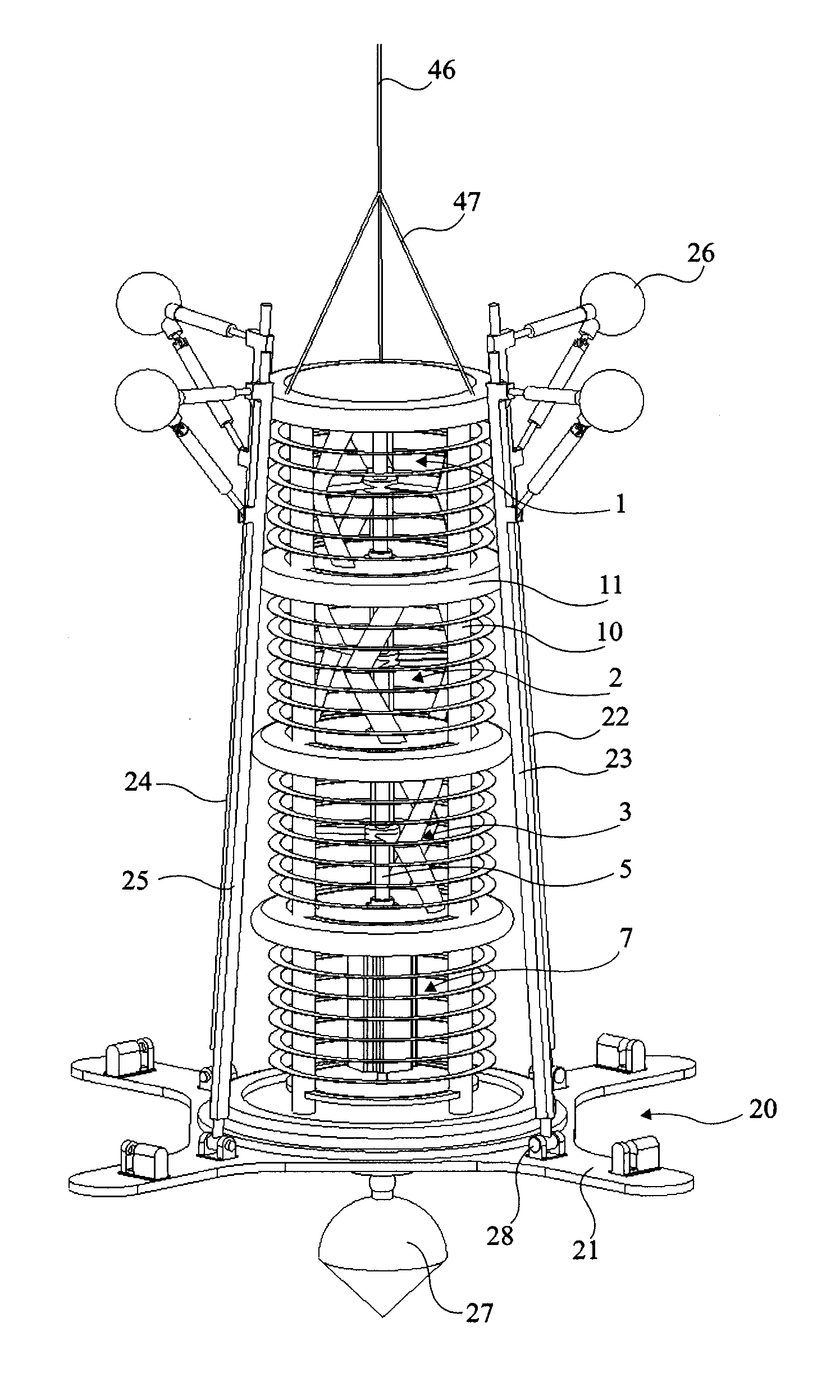
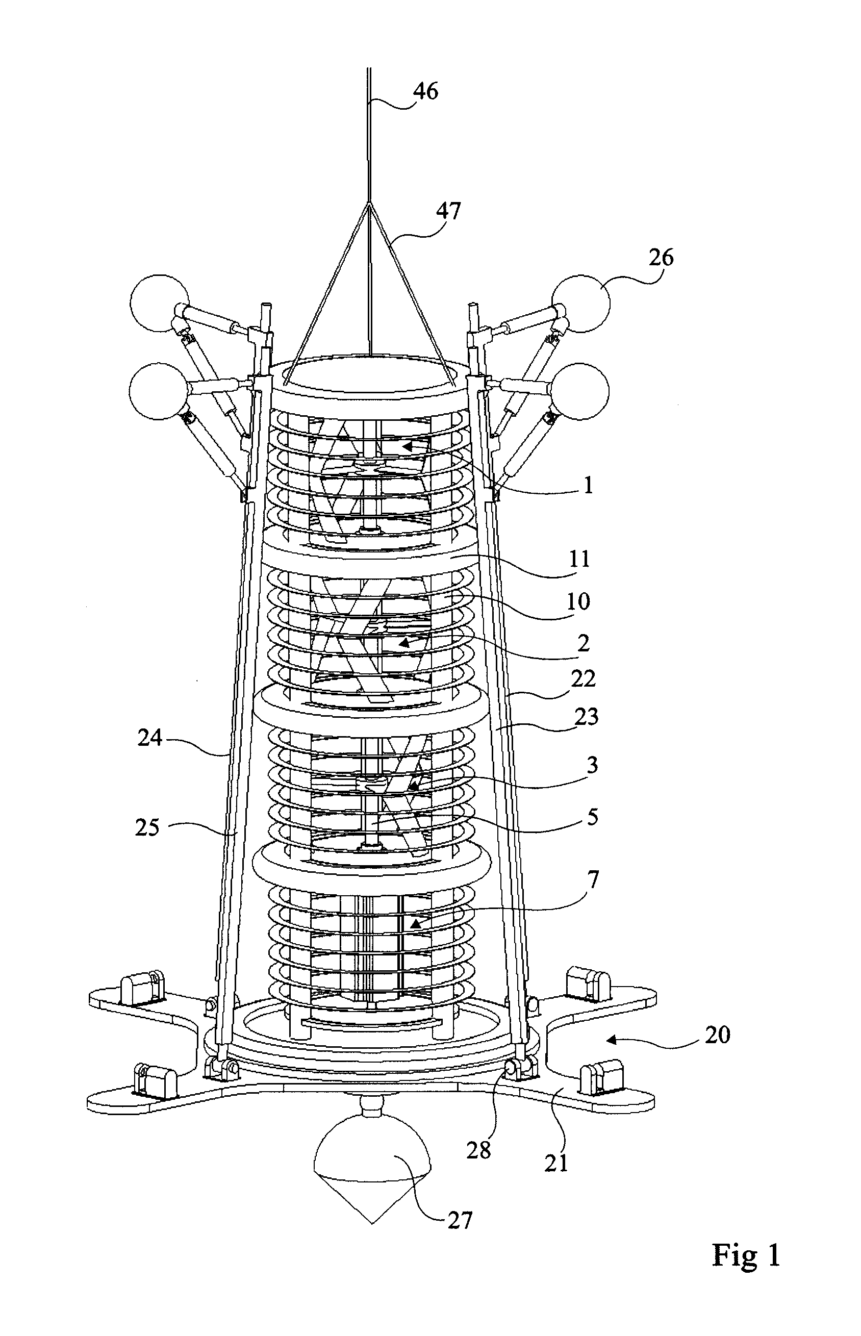
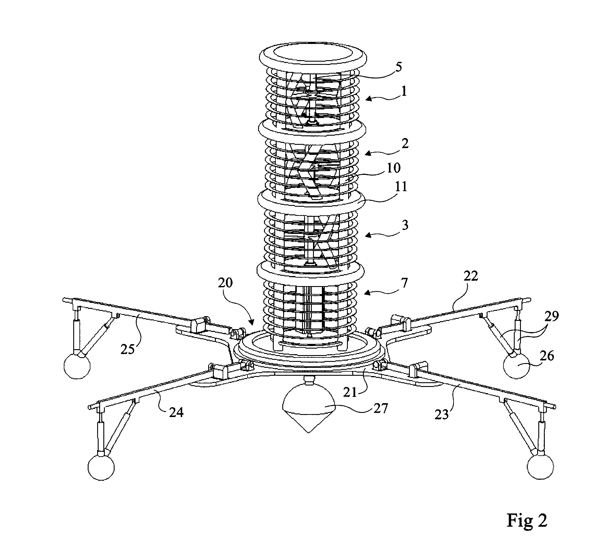
[0047]FIGS. 1 and 2 show an example of a cross-flow turbine engine adapted to a simple submerging system.

[0048]This turbine engine, of the type described in French patent No. 04 / 50209 (B6412—Patent 1), is associated with a holding structure of the type described in French patent application No. 05 / 50420 (B6869—Patent 2) and is provided with a base of the type described in undisclosed French patent application No. 08 / 55593 (B9030—Patent 4).

[0049]This turbine engine comprises three V-shaped wings 1, 2, and 3 attached to a same axis 5 which drives a generator 7. The assembly of the turbines and of the generator is surrounded with a holding structure comprising posts 10 connected by hoops 11 which support bearings maintaining axis 5 between two turbine engines. Preferably, the different elements of holding structure 10, 11 are solidly associated together and with a base 20 to be liftable in one block from the top, moving along the turbine engine and base 20. Base 20 comprises a base pla...


PUM


Abstract

The instant disclosure relates to a system for submerging a hydraulic turbine engine, including an assembly including an elongate transverse flow turbine engine; a carriage for receiving said assembly in a prone position; a ship provided with a winch for supporting the carriage on the deck thereof, the bottom side of the turbine engine facing the stern of the ship, the top side being tied to the winch by a pull line; and jacks for righting the carriage and said assembly to a position that is vertically perpendicular to the stern.

Description

FIELD OF THE INVENTION[0001]The present invention relates to a method and a system for submerging a hydraulic turbine engine down to a seabed.DISCUSSION OF PRIOR ART[0002]Among clean natural energy sources, a currently underexploited energy source corresponds to water currents naturally present around the world: open sea currents, tidal currents, strait and estuary currents, stream or river currents.[0003]Installation methods and systems are a key point for the industrial success of hydraulic turbine engines. They must first enable to safely install hydraulic turbine engines on sites that may reach great depths (down to 200 meters). Second, limiting the machine installation cost is essential. Now, in many currently-used systems, this cost may largely exceed machine manufacturing costs.[0004]Thus, it has been provided to use permanent floating platforms, drilled or anchored, originating from off-shore oil drilling.[0005]It has also been provided to attach the turbines to piles. The d...

Claims


Application Information

Patent Timeline
IPC IPC(8): B63B27/08B65G67/60
CPCF03B17/00Y02E10/38Y02E10/28Y02E10/20Y02E10/30E02B17/02F03B13/10
Inventor ACHARD, JEAN-LUCJAQUIER, THOMASJERONIMO, ZANETTE
Owner ELECTRICITE DE FRANCE
Learn More