Sealing gland

a technology of sealing glands and glands, which is applied in the direction of pipes, mechanical equipment, pipes/joints/fittings, etc., can solve the problems of not being able to easily remove and replace sealants, pipe, wall panels or similar cannot be easily removed and replaced, and not having an easy-to-remove system

Active Publication Date: 2015-12-08
LAKE PROD
View PDF33 Cites 18 Cited by
  • Summary
  • Abstract
  • Description
  • Claims
  • Application Information

AI Technical Summary

Benefits of technology

[0013]a sealing body having an inner membrane for sealing about the elongate member and an outer peripheral region for sealing against the surface, the inner membrane having one or more guides on a side of the membrane arranged to locate adjacent the surface in use (hereinafter: underside), and wherein each guide represents a known elongate member option and facilitates the formation of an aperture through the membrane for suitably receiving the associated elongate member option therethrough in use, and
[0030]an outer peripheral region for sealing against the surface, the inner membrane having one or more guides on a side of the membrane arranged to locate adjacent the surface in use (hereinafter: underside), and wherein each guide represents a known elongate member option and facilitates the formation of an aperture through the membrane for suitably receiving the associated elongate member option there through in use.

Problems solved by technology

Prior art methods that use sealants and similar are messy and time consuming and the sealant cannot be easily removed and replaced, meaning that the pipe, wall panel or similar cannot be easily removed and replaced.
This is not an easily removable system.
This method and the previous one do not stand up well to vibration and flexure of the pipe relative to the flat surface.
Methods that have used boots to date have not resulted in a consistently sealing boot about the pipe and against the bulk head.
The solutions that currently exist with a sealable cut for sealing about an existing pipe and wall share the same problems as the uncut ones together with the added problem that the cut does not seal consistently either.

Method used


Image

  • Sealing gland
  • Sealing gland
  • Sealing gland

Examples


Embodiment Construction

[0088]A preferred embodiment of the present invention will now be described with reference to FIG. 1 through 5.

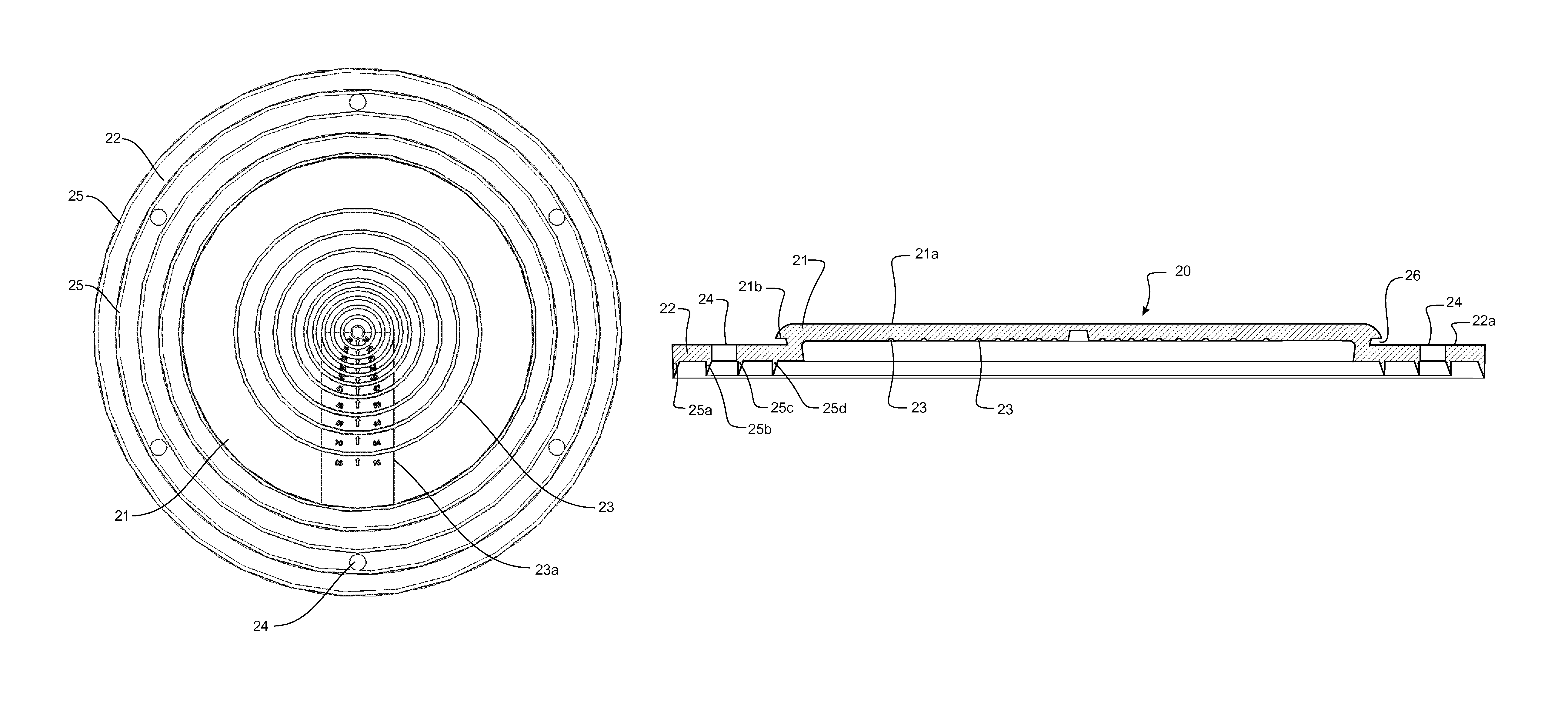
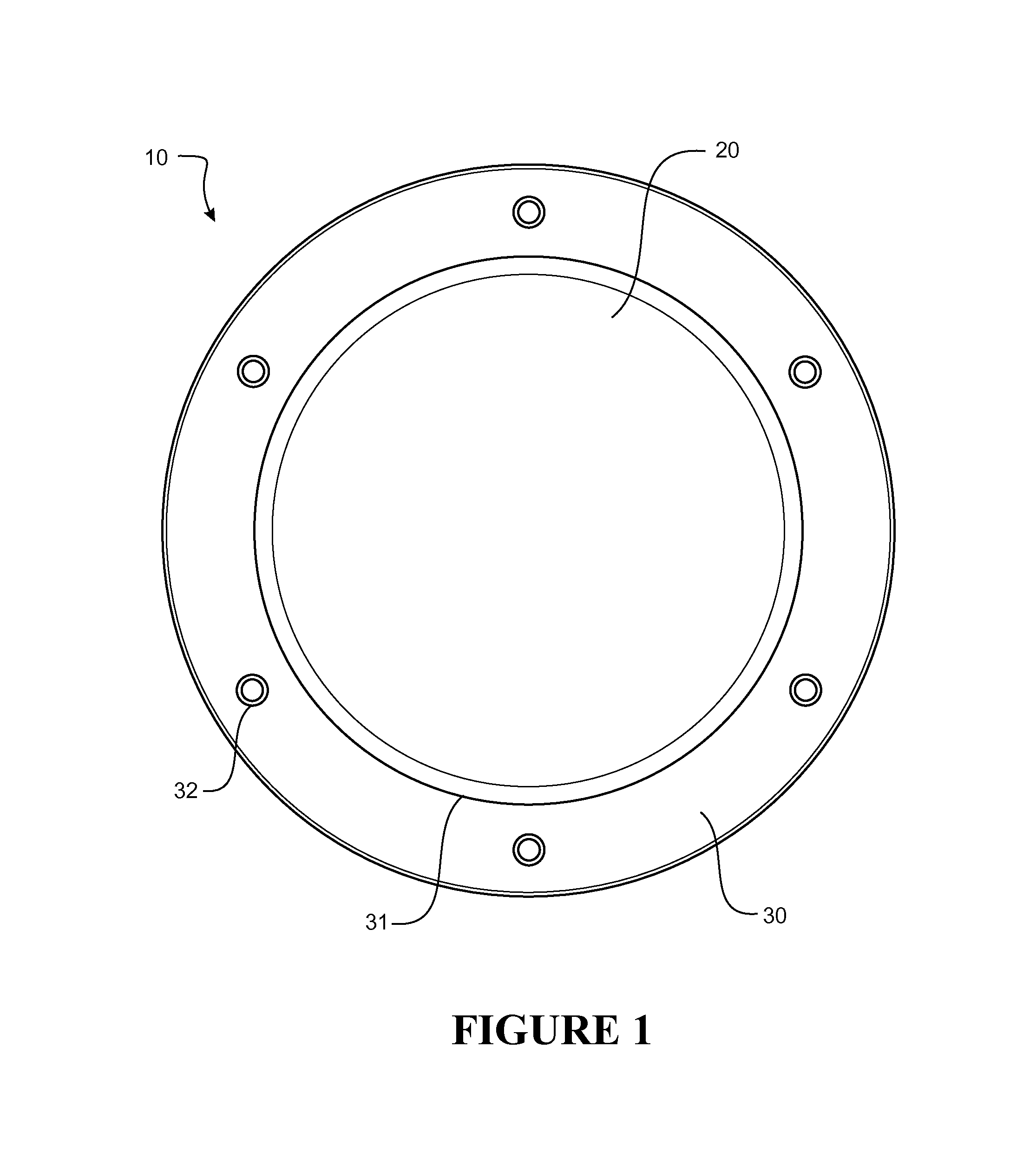
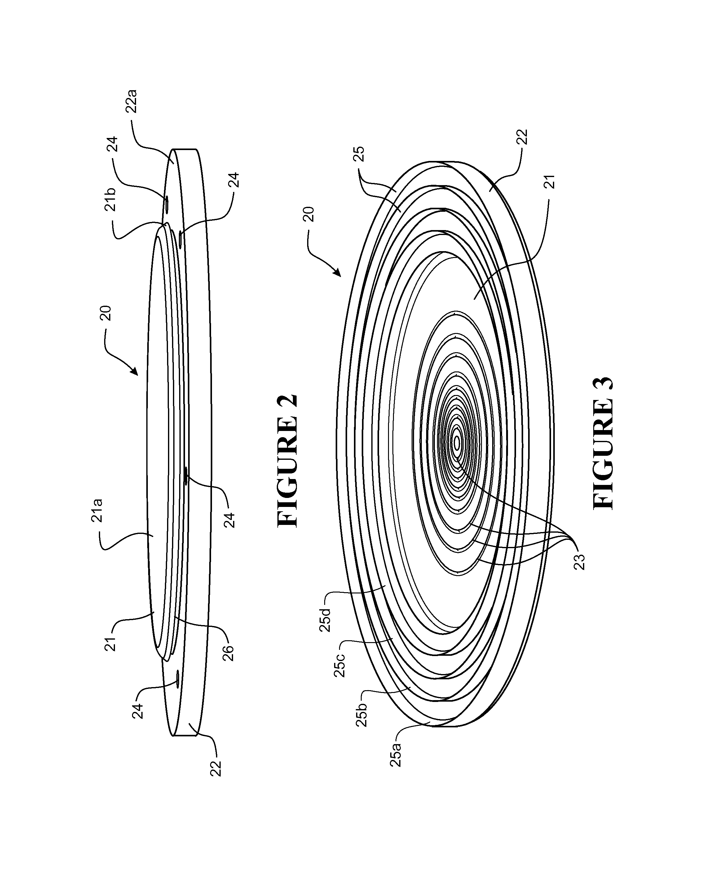
[0089]Referring to FIG. 1, a preferred form sealing gland (10) is shown consisting of a sealing body (20) and a compression ring (30). In use, the sealing gland (10) seals between the outer wall of an elongate member (not shown), such as a pipe or other duct, and a surface through which the elongate member extends. Prior to use, an aperture is formed through the sealing body (20) for receiving and engaging about the elongate member. The sealing body (20) forms the seal between the elongate member and the surface, whilst the compression ring (30) maintains an effective seal by compressing the sealing body (20) as it couples the surface over the body (20). The preferred form sealing gland (10) is formed to seal between an annular member and a flat surface, such as a pipe or duct extending through a ceiling or roof surface. It will be appreciated however that the gland (10) ma...


PUM


Abstract

A sealing gland for sealing between an elongate member and a surface through which the member extends, the gland comprising a sealing body having an inner membrane for sealing about the elongate member and an outer peripheral region for sealing against the surface. The inner membrane has one or more cut guides on an underside of the membrane arranged to locate adjacent the surface in use. Each cut guide represents a known elongate member option and facilitates the formation of an aperture through the membrane for suitably receiving the associated elongate member option there through in use. A compression ring is also provided to couple the surface over the sealing body to compress the sealing body in use and form an effective seal.

Description

[0001]The present application claims convention priority to and the benefit of Japanese patent application No. 2012-225480 entitled “An Improved Sealing Gland” and filed on Sep. 21, 2012, the complete disclosure of which is hereby incorporated by reference in its entirety.FIELD OF INVENTION[0002]The present invention relates to sealing glands and in particular though not solely to sealing glands for sealing the join formed between and about an elongate member such as for example a pipe with a surface, for example a wall, ceiling or floor.BACKGROUND OF THE INVENTION[0003]Specific requirements for clean areas for example in food handling, biologically sensitive areas, or other such areas requiring a clean seal, requires use of a seal that can be cleaned easily, applied easily and become functional easily yet is also consistent in its sealing engagement to both the pipe and the wall, and that is manufactured from inert and chemically resistant materials, so as to not contaminate the im...

Claims


Application Information

Patent Timeline
Patent Type & Authority Patents(United States)
IPC IPC(8): F16L5/08F16L5/02F16L5/10
CPCF16L5/02F16L5/10
Inventor HAYNES, ANDREW LEOGIURGIU, GABRIEL IOAN
Owner LAKE PROD
Why Eureka
Try Eureka