Directive, electrically-small UWB antenna system and method

a technology of directive and small uwb antennas, applied in the direction of individual energised antenna arrays, antennas, electrical equipment, etc., can solve the problems of less stable antennas, impractical hand-held devices, and prohibitively large quarter-wavelength antennas for certain applications, so as to avoid resonance tyranny, improve efficiency, and improve efficiency

Active Publication Date: 2015-12-08
GAN CORP
View PDF15 Cites 10 Cited by
  • Summary
  • Abstract
  • Description
  • Claims
  • Application Information

AI Technical Summary

Benefits of technology

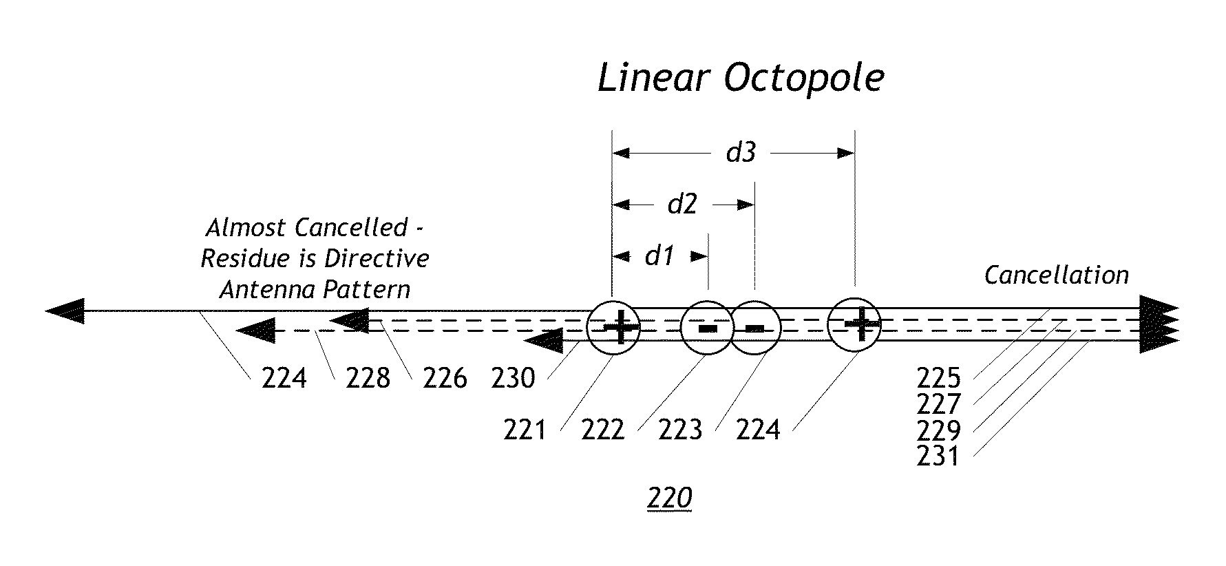
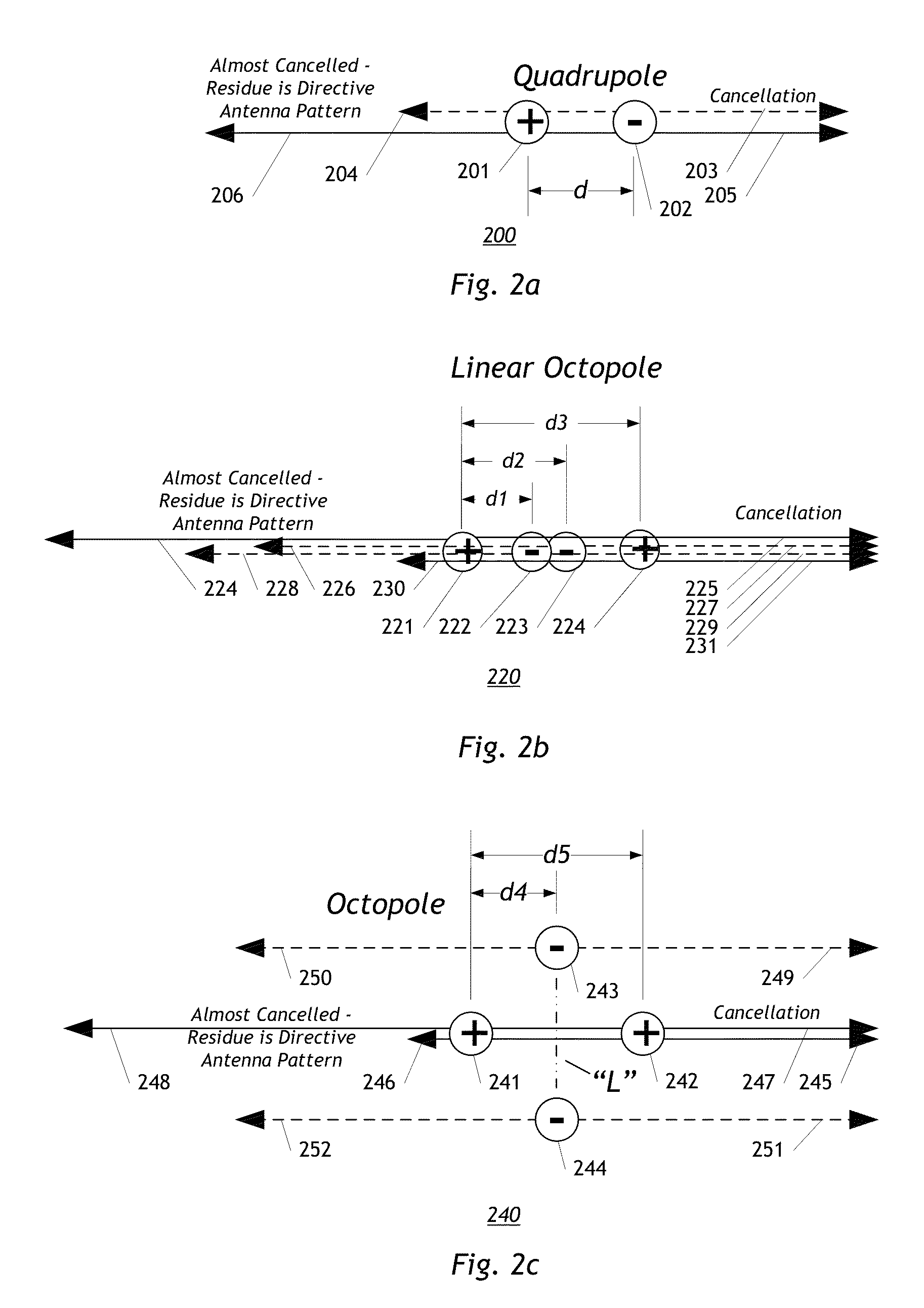
[0007]A directive, electrically-small UWB antenna system and method neatly sidesteps the tyranny of resonance. This system and method employs multipole synthesis to implement electrically-small multipole antennas with ultra-wideband (UWB) stable antenna patterns. In many embodiments, these antennas are directive with at least cardioid-like patterns. Although lossy, embodiments have adequate efficiency to work as receive antennas in the high ambient noise environment of the HF band and below. The present invention also introduces the concept of antenna regeneration to achieve a higher efficiency over a broader bandwidth than has traditionally been thought possible—multiple frequency decades in some cases.

Problems solved by technology

When operated at “low” frequencies, traditional quarter-wavelength antennas become prohibitively large for certain applications.
For example, a quarter-wavelength monopole operating at 10 MHz has a physical size of 7.5 m. This may be acceptable for an outdoor antenna (for instance), but would be impractical for a compact hand-held device.
However, the higher the Q, the narrower the bandwidth and the less stable the antenna.
Particularly high Q antennas exhibit narrow bandwidth and may be thrown off frequency by changes in their surroundings, temperature variations, or other factors.
This fundamental “tyranny of resonance” limits the practical implementation of ultrawideband (UWB), high efficiency, and directional electrically small antenna designs.

Method used


Image

  • Directive, electrically-small UWB antenna system and method
  • Directive, electrically-small UWB antenna system and method
  • Directive, electrically-small UWB antenna system and method

Examples


Embodiment Construction

4.1 Overview of the Invention

[0033]The present invention relates to directive, electrically small antennas and related systems and processes. This disclosure will now describe the present invention more fully in detail with respect to the accompanying drawings, in which the preferred embodiments of the invention are shown. This invention should not, however, be construed as limited to the embodiments set forth herein; rather, they are provided so that this disclosure will be thorough and complete and will fully convey the scope of the invention to those skilled in the antenna arts. Like numbers refer to like elements throughout.

4.2 Directive, Electrically Small Antenna Synthesis

[0034]An ideal square antenna aperture with side of length in wavelength Lλ has directivity D=4πLλ2 and half power beamwidths of 50.8° / Lλ [John D. Kraus, Antennas (3rd ed.), (New York, McGraw-Hill, 2001), p. 147]. Thus, obtaining high directivity usually requires a multiple wavelength dimension aperture—impra...


PUM


Abstract

A directive electrically small antenna (DESA) process and method employs multipole synthesis to implement directive electrically small multipole antennas with ultra-wideband (UWB) stable antenna patterns. Although lossy, embodiments have adequate efficiency to work as receive antennas in the high ambient noise environment of the HF band and below. Employing a process dubbed “antenna regeneration,” energy may be circulated within an antenna by means other than resonance. This enables multiple decade UWB response without the efficiency penalties inherent to traditional resistively-loaded antenna systems. Regenerative antennas can simultaneously achieve the performance of high Q resonant antennas and the bandwidth of resistively loaded antennas.

Description

[0001]Development funded by DARPA under Contract No. W31P4Q-10-C-0078 and by the U.S. Air Force under Contract No. FA8718-09-C-0024. This applications claims priority to Provisional Patent Application 61 / 470,735 filed Apr. 1, 2011.1 BACKGROUND[0002]When operated at “low” frequencies, traditional quarter-wavelength antennas become prohibitively large for certain applications. For example, a quarter-wavelength monopole operating at 10 MHz has a physical size of 7.5 m. This may be acceptable for an outdoor antenna (for instance), but would be impractical for a compact hand-held device. Thus, an antenna designer must employ electrically-small antenna (ESA) techniques in order to transmit and receive signals effectively using an antenna considerably smaller than this natural quarter-wavelength scale.[0003]An ESA is one whose size is on the order of the “radiansphere” or smaller. The radiansphere is the hypothetical sphere of radius λ / 2π centered on the antenna. It marks the transition be...

Claims


Application Information

Patent Timeline
Patent Type & Authority Patents(United States)
IPC IPC(8): H01Q21/20H01Q3/26
CPCH01Q21/20H01Q3/26
Inventor SCHANTZ, HANS GREGORYDEPIERRE, ROBERT EDWARD
Owner GAN CORP
Why Eureka
Try Eureka