
Transmitter, receiver, and controlling method thereof

a technology of transmitter and receiver, applied in the field of transmitter and receiving signal frames, can solve the problems of inability to accurately detect the start point of the preamble within one sample, and the inability to perform channel estimation

Active Publication Date: 2015-12-08
SAMSUNG ELECTRONICS CO LTD
View PDF9 Cites 4 Cited by
  • Summary
  • Abstract
  • Description
  • Claims
  • Application Information

AI Technical Summary

Benefits of technology

[0033]According to various exemplary embodiments of the inventive concept as described above, a receiver may accurately measure a start point of a preamble symbol and frequency offset and estimate a channel based on a PN sequence inserted in the preamble symbol.

Problems solved by technology

Therefore, if synchronization is performed based on the signaling data of the P1 preamble symbol, it is difficult to accurately detect a preamble start point within one sample.
Therefore, a channel estimation may not be performed.
Also, the exemplary embodiments are not required to overcome the disadvantages described above, and an exemplary embodiment may not overcome any of the problems described above.

Method used


Image

  • Transmitter, receiver, and controlling method thereof
  • Transmitter, receiver, and controlling method thereof
  • Transmitter, receiver, and controlling method thereof

Examples


Embodiment Construction

[0048]Exemplary embodiments are described in greater detail with reference to the accompanying drawings.

[0049]In the following description, the same drawing reference numerals may be used for the same elements even in different drawings. The matters defined in the description, such as detailed construction and elements, are provided to assist in a comprehensive understanding of the exemplary embodiments. Thus, it is apparent that the exemplary embodiments can be carried out without those specifically defined matters. Also, well-known functions or constructions are not described in detail since they would obscure the exemplary embodiments with unnecessary detail.

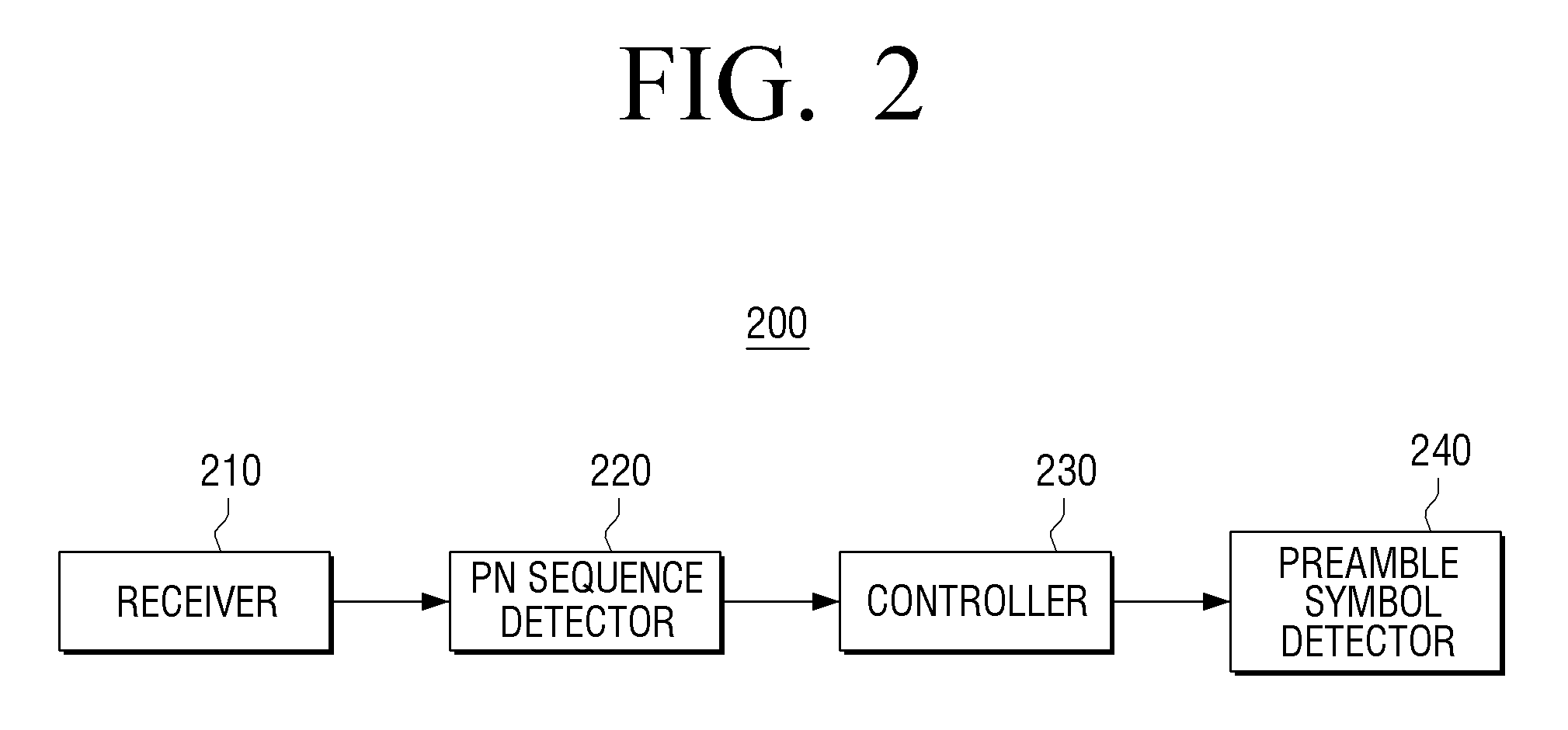
[0050]FIG. 2 is a block diagram illustrating a structure of a receiver 200 according to an exemplary embodiment of the inventive concept.

[0051]Referring to FIG. 2, the receiver 200 includes a receiving unit 210, a pseudo random noise (PN) sequence detector 220, a controller 230, and a preamble symbol detector 240.

[0052]Here, ...


PUM


Abstract

A receiver of a signal frame such as T2 frame used in a DVB-T2 system is provided. The receiver includes: a receiving unit configured to receive a frame including a preamble symbol in which a pseudo random noise (PN) sequence is inserted; a PN sequence detector configured to detect the PN sequence from the received frame; a controller configured to measure a start point of the preamble symbol and frequency offset of the PN sequence inserted in the preamble symbol, based on the detected PN sequence; and a preamble symbol detector configured to detect the preamble symbol according to the measured start point of the preamble symbol and the measured frequency offset of the PN sequence. Therefore, the receiver accurately measures the start point of the preamble symbol and the frequency offset and estimates a channel based on the PN sequence inserted in the preamble symbol.

Description

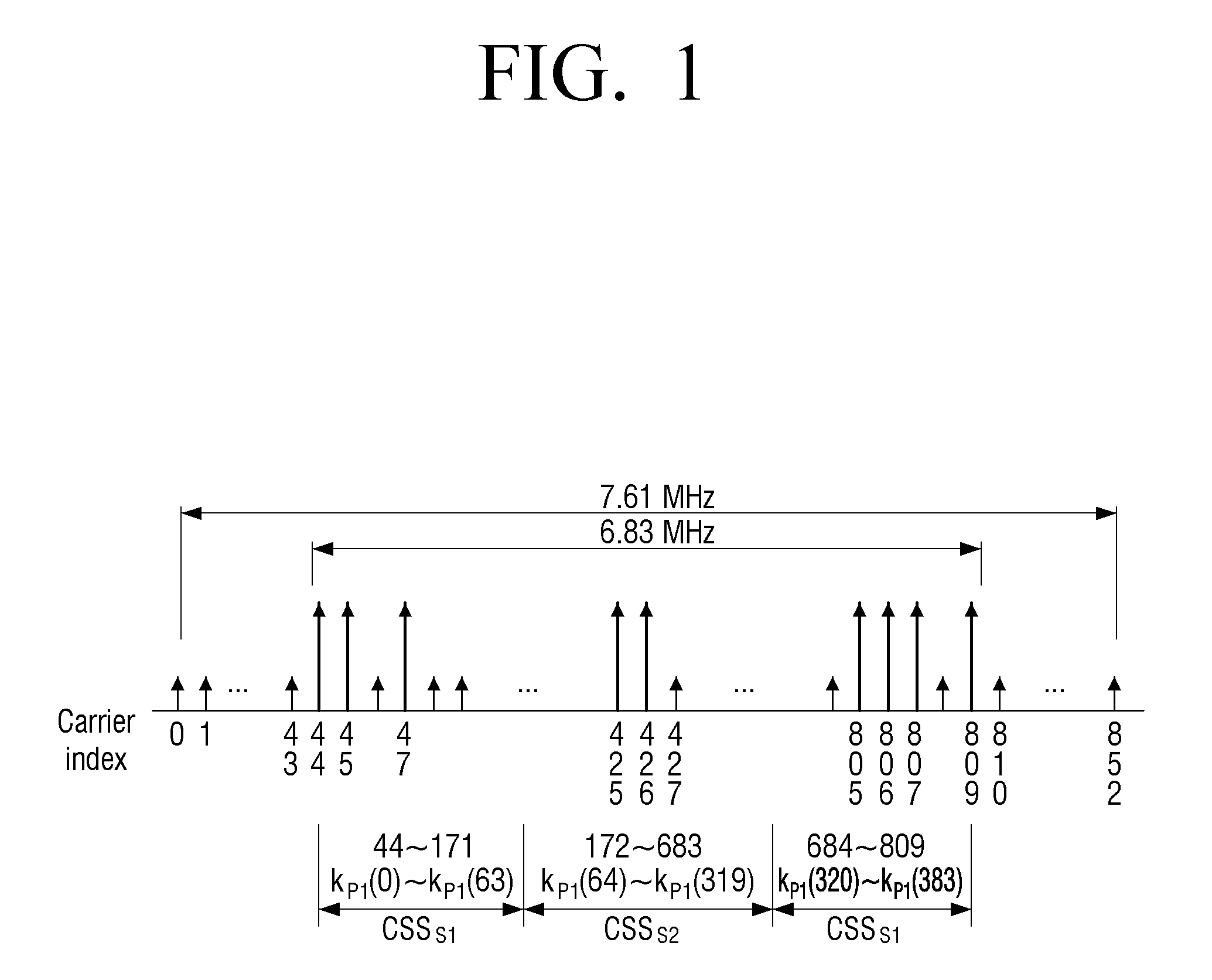
CROSS-REFERENCE TO RELATED APPLICATION(S)[0001]This application claims priority under 35 U.S.C. §119 from Korean Patent Application No. 10-2013-0109542, filed on Sep. 12, 2013, in the Korean Intellectual Property Office, the disclosure of which is incorporated herein by reference in its entirety.BACKGROUND[0002]1. Field[0003]Apparatuses and methods consistent with exemplary embodiments relate to transmitting and receiving signal frames using an orthogonal frequency division multiplexing (OFDM) method.[0004]2. Description of the Related Art[0005]Digital Video Broadcasting the Second Generation Terrestrial (DVB-T2) is a second generation European terrestrial digital broadcasting standard that is established by improving a performance of DVB-T which currently serves as a standard in 35 or more nations including Europe and have started. The DVB-T2 uses newest technologies such as low density parity check (LDPC) codes, 256 quadrature amplitude modulation (256 QAM) modulation method, etc....

Claims


Application Information

Patent Timeline
Patent Type & Authority Patents(United States)
IPC IPC(8): H04B1/00H04L25/02H04L27/26
CPCH04L25/0224H04L27/2602H04L27/2656H04L27/2613H04L27/2657H04L27/2662H04L27/34H04L1/0057H04L27/26025H04J13/0022H04L25/0202H04L27/2655
Inventor OH, YOUNG-HOYUN, SUNG-RYUL
Owner SAMSUNG ELECTRONICS CO LTD
Learn More