Generation of graphical feedback in a computer system

a computer system and graphical feedback technology, applied in the field of information presentation, can solve the problems of severe asymmetry in communication bandwidth in human computer interaction, substantial change in input ditto, and difficulty for users, and achieve the effect of high precision and high efficiency

Active Publication Date: 2015-12-15
TOBII TECH AB
View PDF14 Cites 12 Cited by
  • Summary
  • Abstract
  • Description
  • Claims
  • Application Information

AI Technical Summary

Benefits of technology

[0008]The object of the present invention is therefore to offer a solution, which alleviates the above problems and thus provides a user friendly and ergonomically appropriate means to control a computer system with high precision, and in a highly efficient manner.

Problems solved by technology

Nevertheless, while the output bandwidth has multiplied several times, the input ditto has been substantially unaltered.
Consequently, a severe asymmetry in the communication bandwidth in the human computer interaction has occurred.
The first two solutions above are problematic because by employing these strategies it may be difficult for the user, who perhaps is a handicapped person, to control his / her head or gaze with sufficiently high precision to position the cursor at the desired place on the screen.
Furthermore, even if the user is capable of controlling his / her body with very high precision, various imperfections in the tracking equipment may introduce measurement errors when registering the eyes / head position and the gaze point respectively, so that it still becomes difficult, or at least wearying to achieve the intended result.
Nevertheless, operation of such a mechanical device is associated with other problems, for instance related to fatigue, repetitive strain injuries etc.
Moreover, a mechanical input device, such as a conventional mouse, is relatively slow and requires a certain operating space, either on the desktop or on a device surface (in the case of a laptop).
Sometimes, no such space is available, or providing the required space is problematic.

Method used


Image

  • Generation of graphical feedback in a computer system
  • Generation of graphical feedback in a computer system
  • Generation of graphical feedback in a computer system

Examples


Embodiment Construction

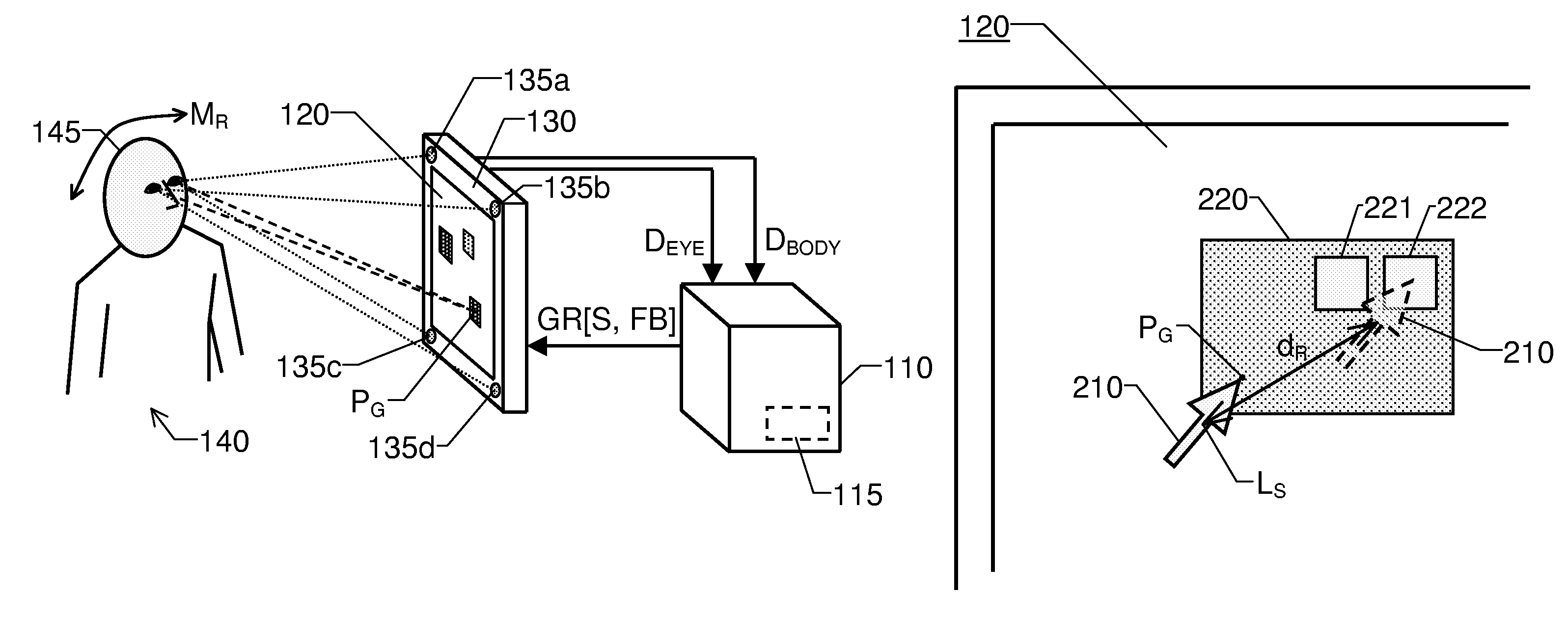
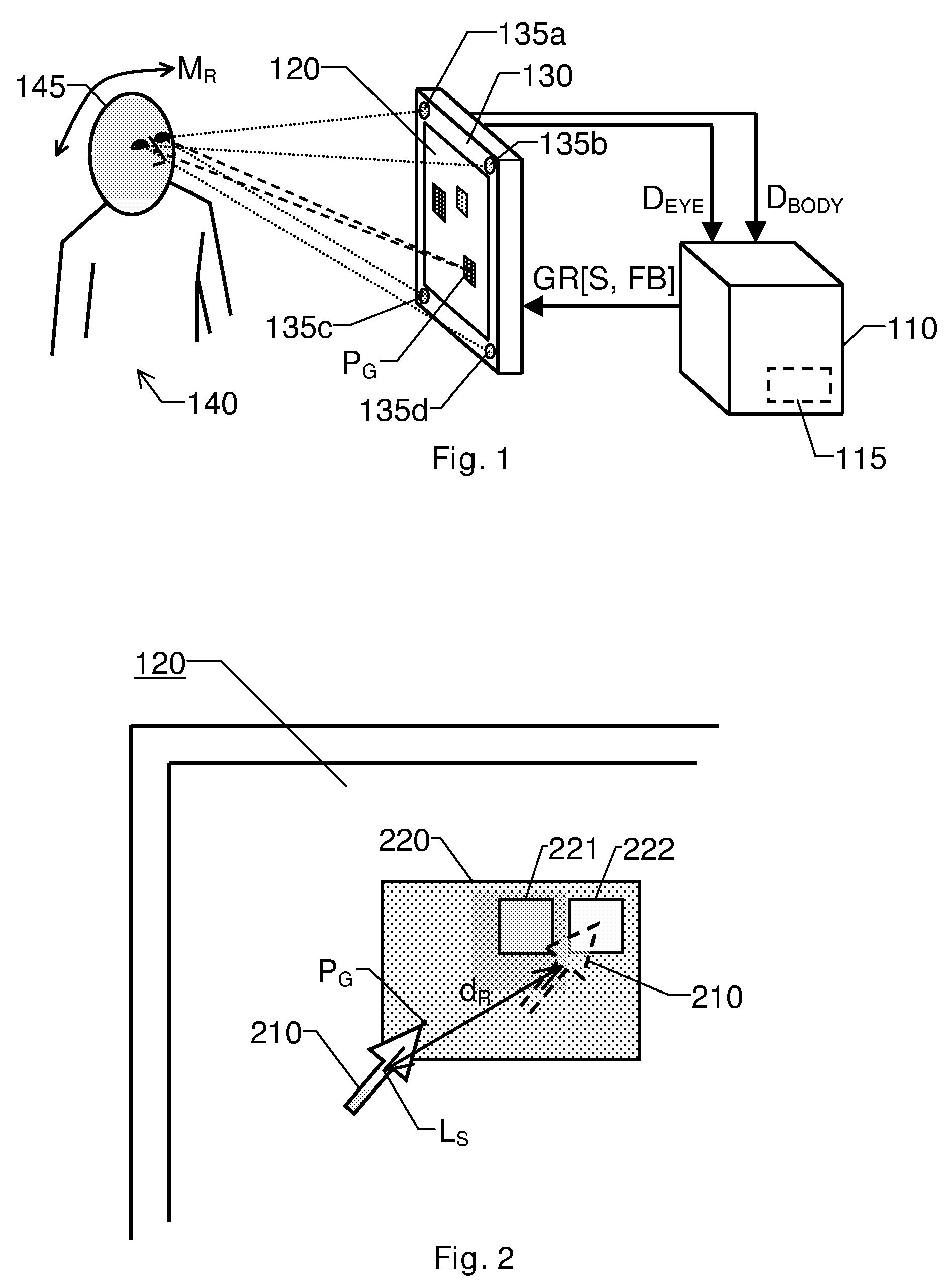
[0029]FIG. 1 shows an overview picture of a typical use-case according to the invention. Here, a user 140 controls a computer system by means of eye movements and movements of a particular body part.

[0030]The system includes a data processing unit 110, a display 120 and an eye tracker 130, which is either integrated in the display 120 (as shown in the figure), or a separate unit. The eye tracker 130 is adapted to register the user's 140 gaze point PG with respect to the display 120. To this aim, the eye tracker 130 is preferably equipped with one or more imaging devices 135a and 135b. It is generally advantageous if the eye tracker 130 also includes, or is associated with, one or more light sources 135c and 135d for emitting light, e.g. in the infrared or near infrared spectrum, towards the user 140. The eye tracker 130 is adapted to produce eye tracking data DEYE describing the gaze point PG, and to forward this data DEYE to the data processing unit 110.

[0031]The data processing un...


PUM


Abstract

The present invention relates to control of a computer system, which includes a data processing unit, a display and an eye tracker adapted to register a user's gaze point with respect to the display. The data processing unit is adapted to present graphical information on the display, which includes feedback data reflecting the user's commands entered into the unit. The data processing unit is adapted to present the feedback data such that during an initial phase, the feedback data is generated based on an absolute position of the gaze point. An imaging device of the system is also adapted to register image data representing movements of a body part of the user, and to forward a representation of the image data to the data processing unit. Hence, during a phase subsequent to the initial phase, the data is instead generated based on the image data.

Description

CROSS-REFERENCE TO RELATED APPLICATIONS[0001]This application is the U.S. national phase of PCT Appln. No. PCT / SE2007 / 050024 filed Jan. 17, 2007 which claims priority to Swedish application SE 0600208-3 filed Feb. 1, 2006. This application also claims the benefit of U.S. provisional application Ser. No. 60 / 764,712 filed Feb. 2, 2006.THE BACKGROUND OF THE INVENTION AND PRIOR ART[0002]The present invention relates generally to presentation of information representing graphical feedback in response to user commands entered into a computer system. More particularly the invention relates to a computer system according to the preamble of claim 1 and a method according to the preamble of claim 12. The invention also relates to a computer program according to claim 22 and a computer readable medium according to claim 23.[0003]Human computer interaction has been revolutionized by the graphical user interface (GUI). Namely, this interface provides an efficient means for presenting information...

Claims


Application Information

Patent Timeline
Patent Type & Authority Patents(United States)
IPC IPC(8): G06F3/033G09G5/08G06F3/01G06F3/038G06F3/0346G06F3/0481
CPCG06F3/013G06F3/017G06F3/0481G06F3/0304G06F3/167G09G5/08
Inventor ELVESJO, JOHNOLSSON, ANDERSSAHLEN, JOHAN
Owner TOBII TECH AB
Why Eureka
Try Eureka