Image evaluation device, image evaluation method and program storage medium

a technology of image evaluation and program storage medium, which is applied in the direction of image analysis, image enhancement, instruments, etc., can solve the problems of document speed and accuracy, document quality and accuracy, and the degree of this kind of line defect often exceeds the acceptable range, so as to achieve quick and accurate determination

Active Publication Date: 2015-12-15
FUJIFILM CORP
View PDF13 Cites 15 Cited by
  • Summary
  • Abstract
  • Description
  • Claims
  • Application Information

AI Technical Summary

Benefits of technology

[0010]The present invention has been made in consideration of the above circumstance, and provides an image evaluation device, an image evaluation method, and a program storage medium that may quickly and accurately determine whether or not a printout includes an image having an inacceptable line defect.

Problems solved by technology

There is a case in which part of printouts printed by a printing machine are defective printouts.
The line defect is caused by, for example, a problem such as a structural problem of the printing machine.
Further, most of line defects caused by the problem of the printing machine tend to appear in a line form along a specific direction.
The degree of this kind of line defect often exceeds an acceptable range.
However, the methods disclosed in the above documents do not provide quick and accurate determination of whether or not a line defect caused by the structural problem of the printing machine is an inacceptable line defect.

Method used


Image

  • Image evaluation device, image evaluation method and program storage medium
  • Image evaluation device, image evaluation method and program storage medium
  • Image evaluation device, image evaluation method and program storage medium

Examples


first embodiment

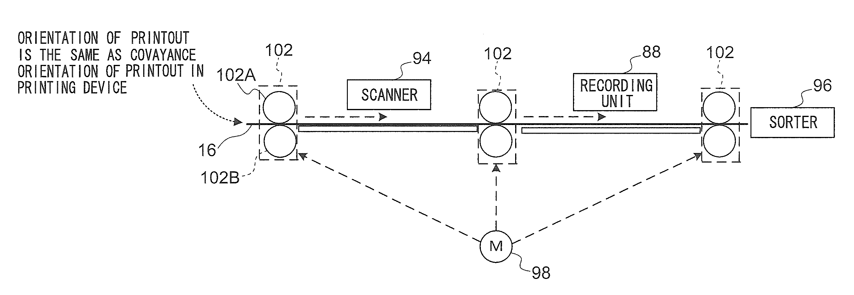
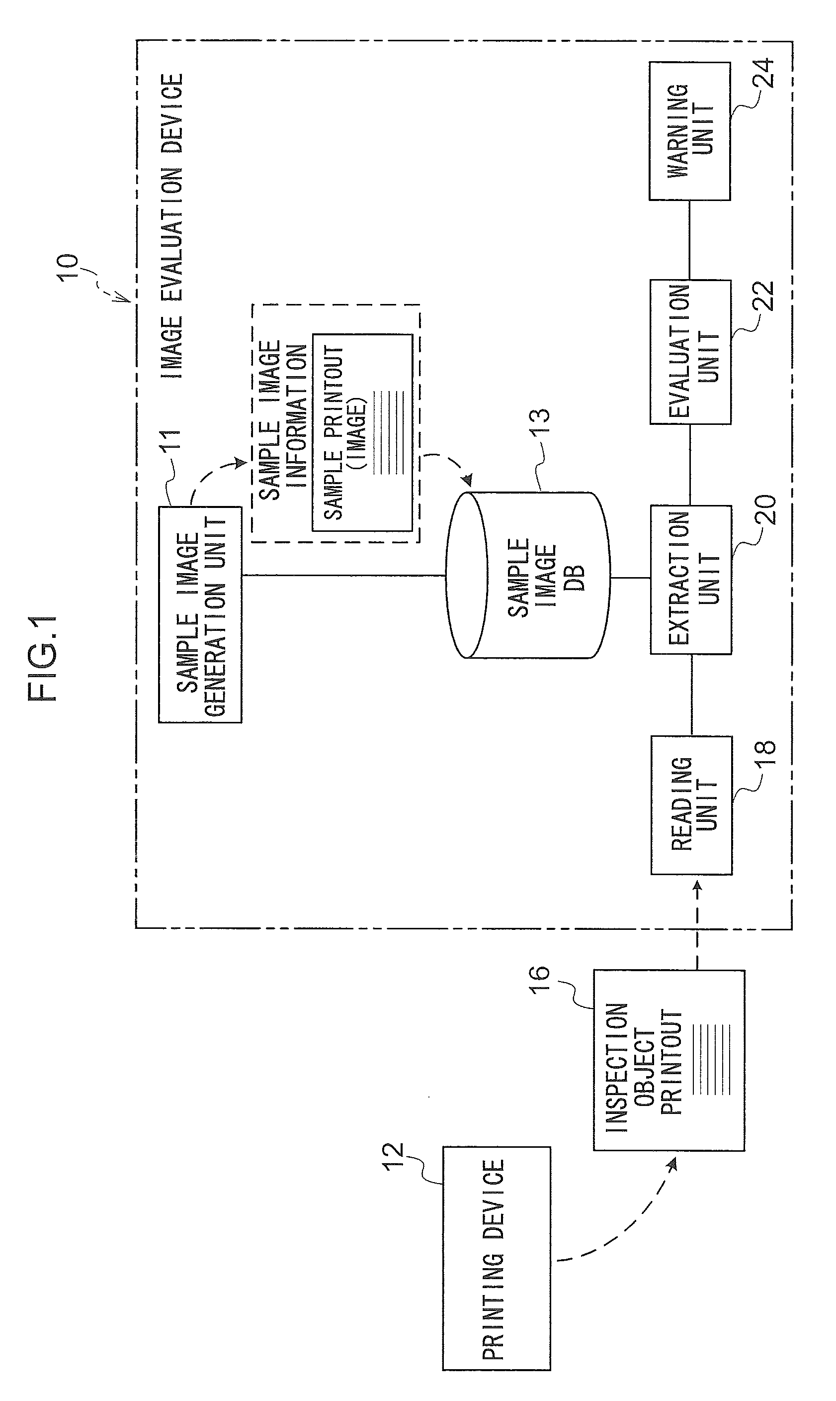
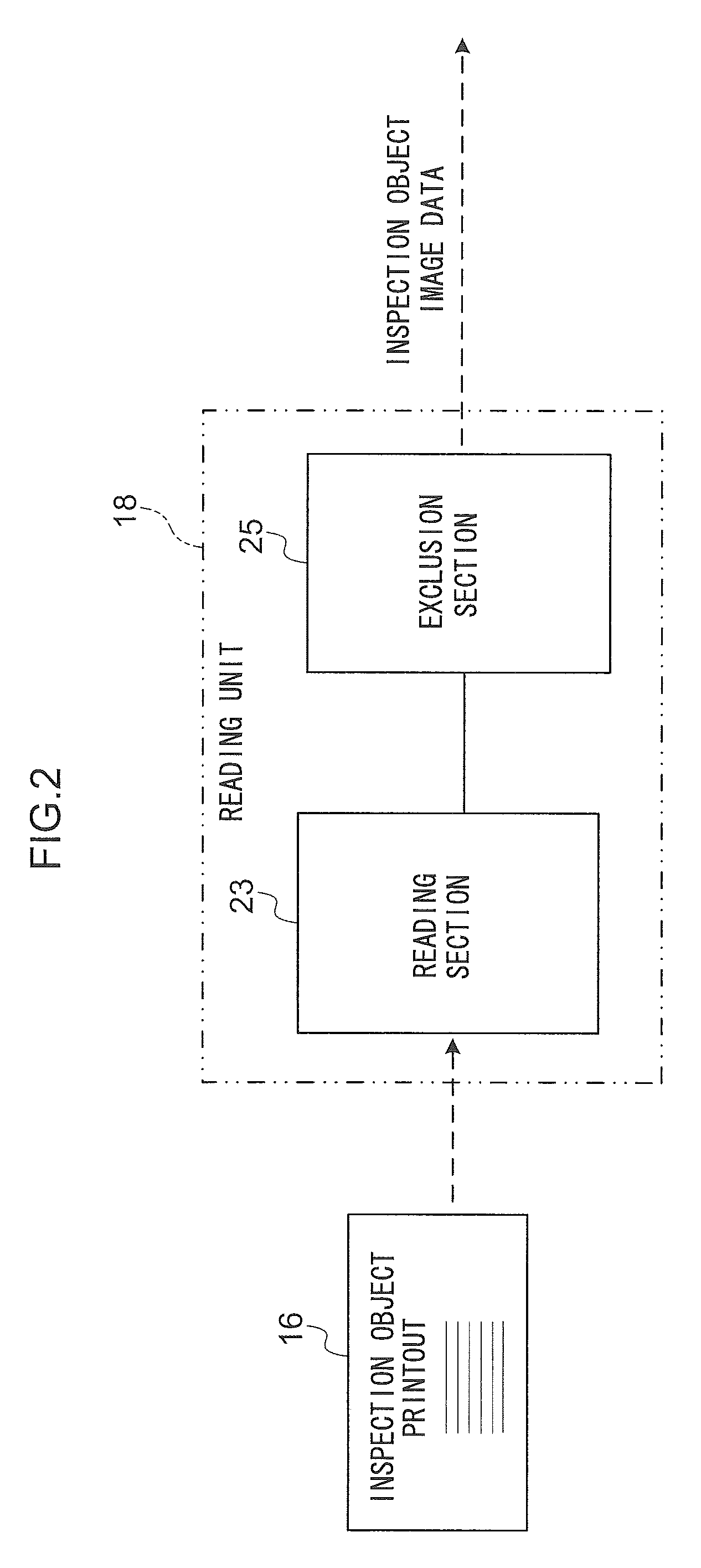
[0120]FIG. 1 illustrates an example of main functional components of an image evaluation device 10 according to a first embodiment. As illustrated in FIG. 1, the image evaluation device 10 is a device that evaluates an image of a printout printed by a printing device 12. After image information (data) representing an image is input, the printing device 12 forms a printout by printing an image that is expressed by the image data on a recording medium such as a recording sheet.

[0121]A single-pass inkjet printer is used as the printing device 12 in the first embodiment; however, embodiments are not limited thereto. For example, a shuttle-scan inkjet printer may be used instead of the single-pass inkjet printer. Further, a xerographic printer, a thermal head printer, a magnetographic printer, a machine plate printing machine, or the like may be used instead of the inkjet printer. The printing device 12 of the first embodiment is configured by an inkjet printer that conveys recording she...

second embodiment

[0255]In the first embodiment, an example in which the visibility of a line defect is evaluated using a visual model with mask effect has been described. In the present second embodiment, a case in which the visibility of a line defect is evaluated by a statistical method will be described. In the description of the second embodiment, the components common to the first embodiment will be denoted by the same reference numerals and descriptions thereof will be omitted, and only the portions different from the first embodiment will be described.

[0256]FIG. 23 illustrates an example of main functional components of an evaluation unit 22A according to the second embodiment. As illustrated in FIG. 23, the evaluation unit 22A differs from the evaluation unit 22 illustrated in FIG. 4 in that the specific component decomposing section 38, the second image combining section 40, and the visual model evaluation section 42 are omitted. Further, the evaluation unit 22A differs from the evaluation ...

third embodiment

[0286]In the first embodiment, the warning unit 24 determines whether or not the level of the visibility of a line defect is a level that requires a warning by referring to the reference data of the reference DB 46. In the third embodiment, the determination of whether or not the level of visibility is a level that requires a warning is performed according to the characteristics of a customer. In the following description, the same components as those described in the first embodiment will be denoted by the same reference numerals and the description thereof will be omitted, and only the portions different from the first embodiment will be described.

[0287]FIG. 30 illustrates an example of main functional components a warning unit 24A according to the third embodiment. The warning unit 24A illustrated in FIG. 30 differs from the warning unit 24 illustrated in FIG. 5 in that a warning determination section 44A is provided in place of the warning determination section 44. Further, alth...


PUM


Abstract

An image evaluation device includes a storage unit that stores sample image data that represent a virtual sample image simulating a sample image included in a sample printout that is recognized as a non-defective printout; a reading unit that reads an inspection object image included in an inspection object printout obtained by printing the sample image on a recording medium by a printing device using image data representing the sample image; an extraction unit that extracts a line defect including a linear pattern formed in a specific direction from the inspection object image represented by inspection object image data, based on a difference value between the sample image data and the inspection object image data; and an evaluation unit that evaluates a visibility of the line defect extracted by the extraction unit.

Description

CROSS-REFERENCE TO RELATED APPLICATION[0001]This application claims priority under 35 USC 119 from Japanese Patent Application No. 2012-218710 filed on Sep. 28, 2012, the disclosure of which is incorporated by reference herein.BACKGROUND OF THE INVENTION[0002]1. Technical Field[0003]The present invention relates to an image evaluation device, an image evaluation method, and a program storage medium.[0004]2. Related Art[0005]There is a case in which part of printouts printed by a printing machine are defective printouts. Therefore, an inspection method of determining the quality of a printout is proposed, in which images are obtained by scanning and reading printouts, and determination is made as to whether or not there is an image of defective printouts that cannot be ignored in the read images (for example, see Japanese Patent Application Laid-Open (JP-A) Nos. 2007-033247 and 2006-139777).[0006]JP-A No. 2007-033247 discloses an inspection method of determining image quality by form...

Claims


Application Information

Patent Timeline
Patent Type & Authority Patents(United States)
IPC IPC(8): G06K9/00H04N1/00
CPCG06K9/00483H04N1/00005H04N1/0005H04N1/00015H04N1/00034H04N1/00047H04N1/00074G06T2207/10024G06T7/001G06T2207/20224G06T2207/30144G06V30/418
Inventor YAMAGISHI, HIDEKI
Owner FUJIFILM CORP
Why Eureka
Try Eureka