Flexible display device having flexible display substrate with bending area between display area and peripheral circuit area

a display device and flexible technology, applied in the field of flexible display devices, can solve problems such as high complexity, and achieve the effect of reducing the resilient force of the flexible display device and reducing the tensile stress in the components

Active Publication Date: 2015-12-15
LG DISPLAY CO LTD
View PDF20 Cites 41 Cited by
  • Summary
  • Abstract
  • Description
  • Claims
  • Application Information

AI Technical Summary

Benefits of technology

[0015]In one embodiment, the flexible display device further includes a polarizer on the flexible display substrate. The polarizer is formed with a pattern along the bending area to provide flexibility to the polarizer in the bending area.
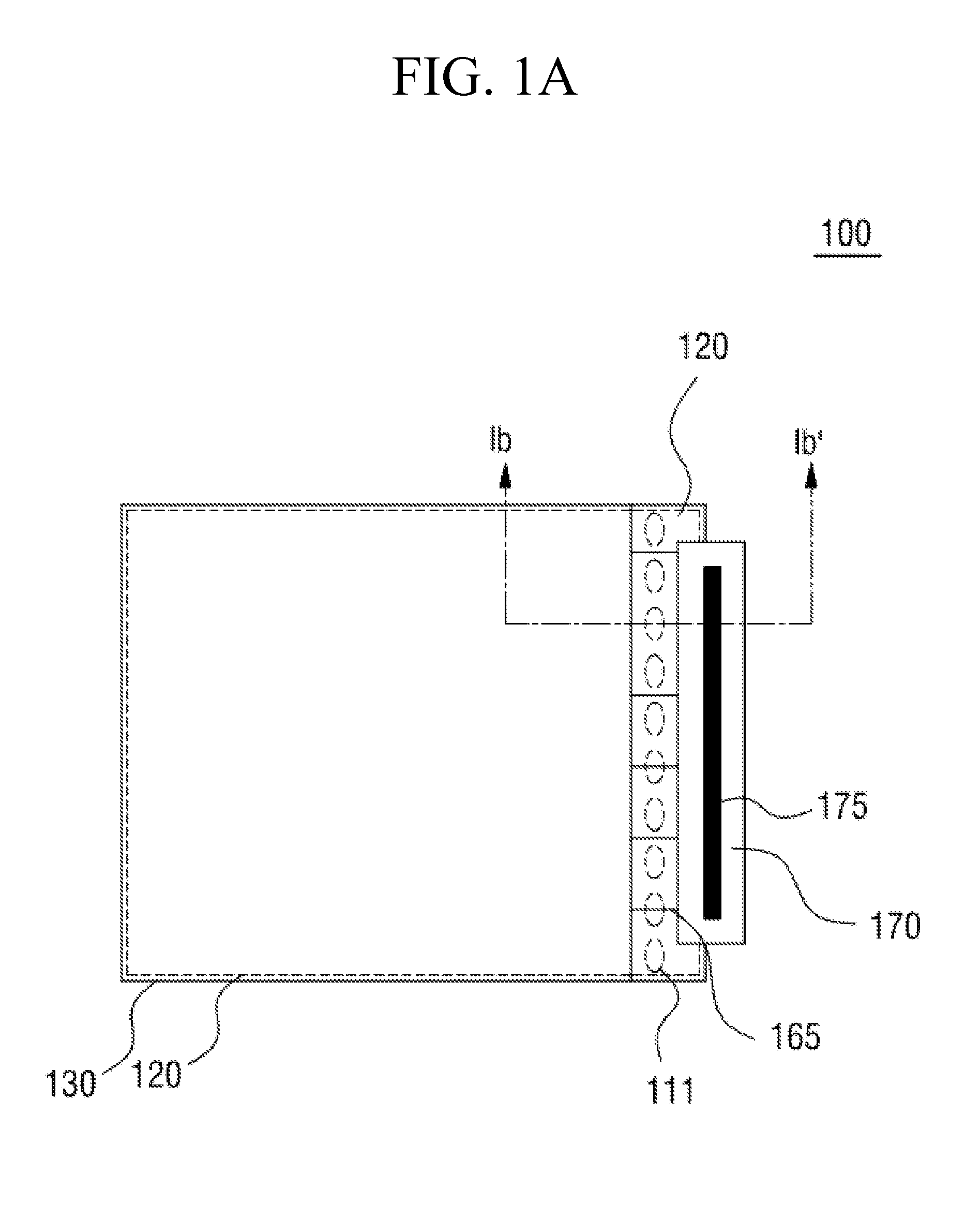
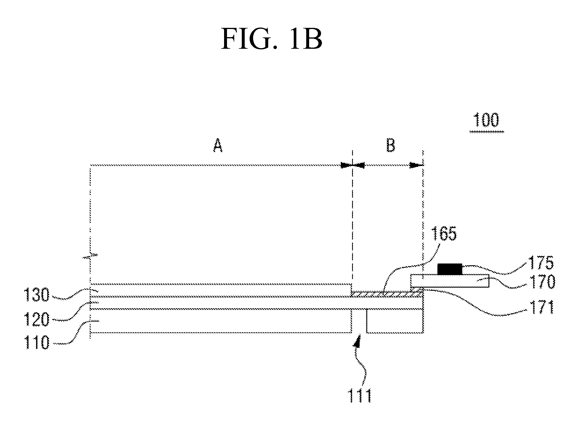
[0018]In one embodiment, the flexible display device further includes a layer on the components for transmitting the signals in the peripheral circuit area to reduce tensile stress in the components when bending occurs in the bending area.
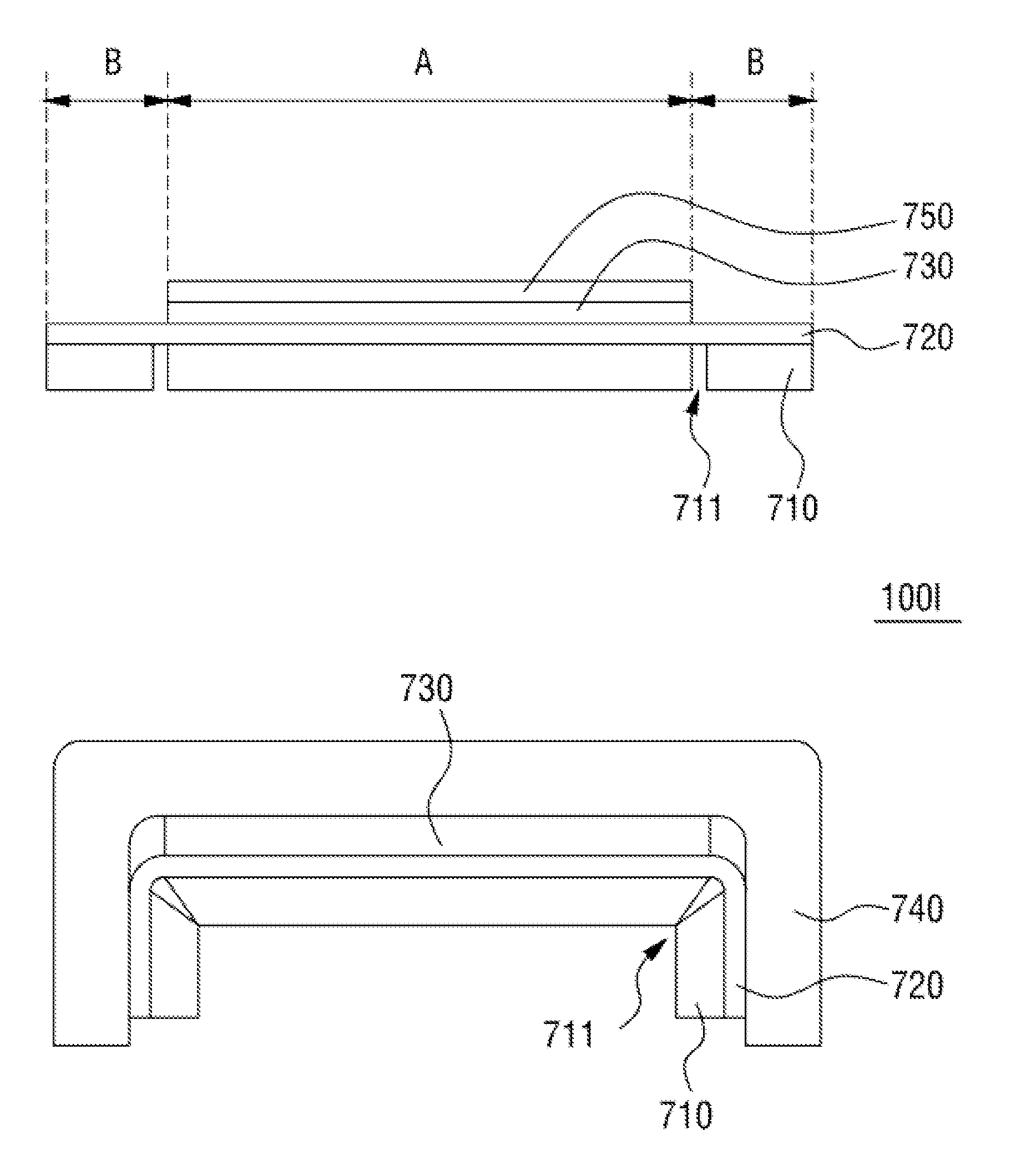
[0019]Embodiments also relate to a flexible display device that includes a flexible display substrate and a support substrate disposed on the flexible display substrate. The flexible display substrate has a display area and a peripheral circuit area. The display area is juxtaposed to a peripheral circuit area. A support substrate is disposed on the flexible display substrate. The support substrate has a bending pattern to provide flexibility at a bending area of the support substrate and to reduce resilient force of the flexible display device. The bending area corresponds to a boundary between the display area and the peripheral circuit area of the flexible display substrate.

Problems solved by technology

Various kinds of highly complicated technology, such as wire positioning, line width setting, and signal transfer, are required to realize a narrow bezel.

Method used


Image

  • Flexible display device having flexible display substrate with bending area between display area and peripheral circuit area
  • Flexible display device having flexible display substrate with bending area between display area and peripheral circuit area
  • Flexible display device having flexible display substrate with bending area between display area and peripheral circuit area

Examples


Embodiment Construction

[0060]Embodiments of the present invention will be described in detail below with reference to the accompanying drawings. It is noted that the drawings of the present application are provided for illustrative purposes only and, as such, the drawings are not drawn to scale. In the following description, numerous specific details are set forth, such as particular structures, components, materials, dimensions, processing steps and techniques, in order to provide an understanding of the various embodiments of the present disclosure. However, it will be appreciated by one of ordinary skill in the art that the various embodiments of the present disclosure may be practiced without these specific details. In other instances, well-known structures or processing steps have not been described in detail in order to avoid obscuring the present disclosure.

[0061]It will be understood that when an element as a layer, region or substrate is referred to as being “on” another element, it can be direct...


PUM

PropertyMeasurementUnit
bending angleaaaaaaaaaa
angleaaaaaaaaaa

Abstract

A flexible display device and a method of manufacturing the same are provided. The flexible display device comprises a first flexible substrate including a display area including an organic light emitting layer, and a peripheral circuit area, and a second flexible substrate coming in contact with the first flexible substrate and including a pattern for facilitating bending thereof, wherein the second flexible substrate has a certain shape according to the pattern, and the first flexible substrate has a shape corresponding to the certain shape. Various embodiments of the present invention provide a flexible display device capable of realizing a narrow bezel-type or bezel-free display device and simultaneously realizing improved types of design, facilitating bending of a bezel area so as to realize a narrow bezel-type or bezel-free display device, and minimizing damage to an area to be bent.

Description

CROSS-REFERENCE TO RELATED APPLICATION[0001]This application claims priority to and the benefit of Korean Patent Application No. 2012-0155873, filed on Dec. 28, 2012, the disclosure of which is incorporated herein by reference in its entirety.BACKGROUND[0002]1. Field of the Invention[0003]The present invention relates to a flexible display device, and more particularly to a narrow bezel or a bezel-free flexible display device and a method of manufacturing the same.[0004]2. Discussion of Related Art[0005]Display devices used in monitors of computers, TVs, and cell phones include organic light emitting display devices (OLEDs) and plasma display panels (PDPs), both of which autonomously emit light, and liquid crystal display devices (LCDs) requiring a separate light source, etc.[0006]In recent years, flexible display devices manufactured using materials exhibiting inflexibility, such as flexible materials (i.e., plastics), to display an image even when bent like paper have received att...

Claims


Application Information

Patent Timeline
Patent Type & Authority Patents(United States)
IPC IPC(8): H01L29/08H01L51/00H01L35/24H01L27/14H01L29/04H01L29/18H01L33/00G09G5/00G06F3/038H01J63/04H01J1/62G02F1/1345
CPCH01L51/0097H01L2251/5338Y02E10/549H10K77/111H10K2102/311G06F1/1652G09F9/301G06F1/1618G06F1/1641H10K50/84H10K50/844H10K50/868H10K50/8426H10K59/12H10K59/128H10K59/131H10K2102/00
Inventor LEE, CHANWOOPARK, JONGHYUNKIM, TAEWOOCHOI, JAEKYUNGYOUN, SANGCHEONMIN, SUNGJOONKWON, SEYEOULLEE, KWONHYUNG
Owner LG DISPLAY CO LTD
Why Eureka
Try Eureka