
Shaving device with improved contour following

a contour following and shaving device technology, applied in the field of shaving head, can solve the problems of changing stretching and compressing of the skin, unable to follow purely convex and concave contours, and a non-uniform skin pressure distribution between the skin and the cutting unit, so as to improve the shaving effect and experience, and the stiffness of the second pivot construction is lower

Active Publication Date: 2015-12-22
KONINK PHILIPS ELECTRONICS NV
View PDF24 Cites 9 Cited by
  • Summary
  • Abstract
  • Description
  • Claims
  • Application Information

AI Technical Summary

Benefits of technology

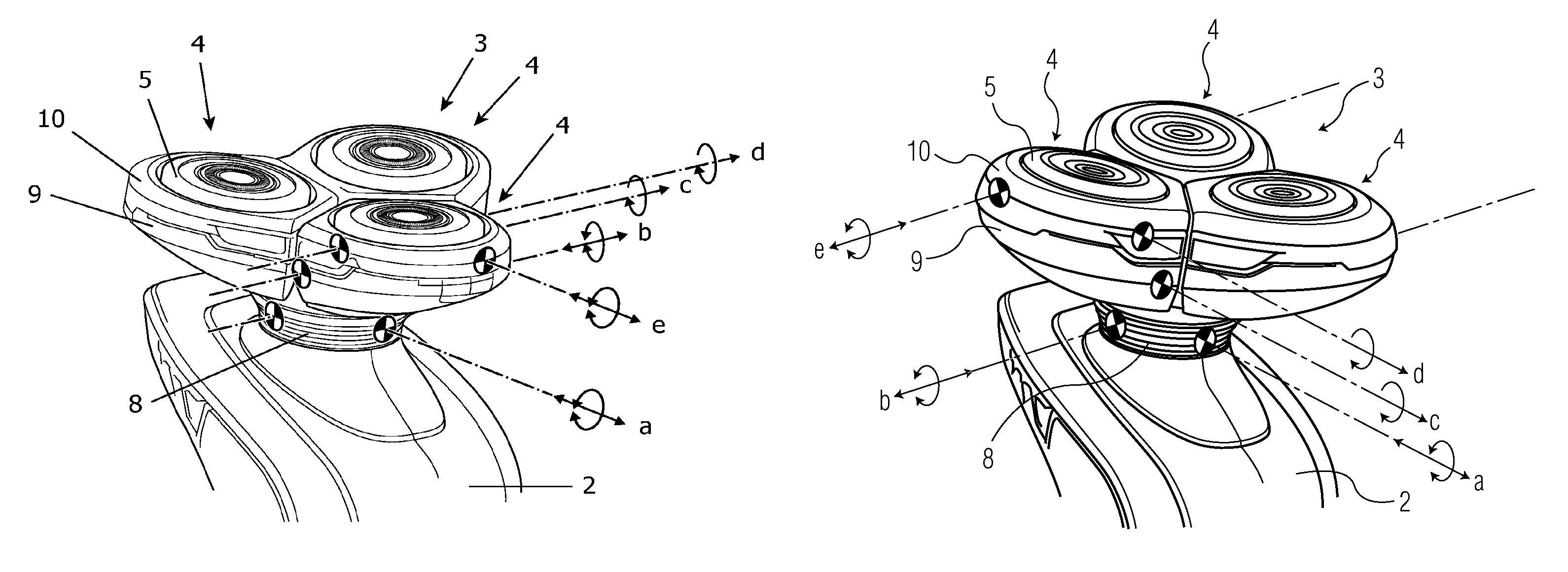
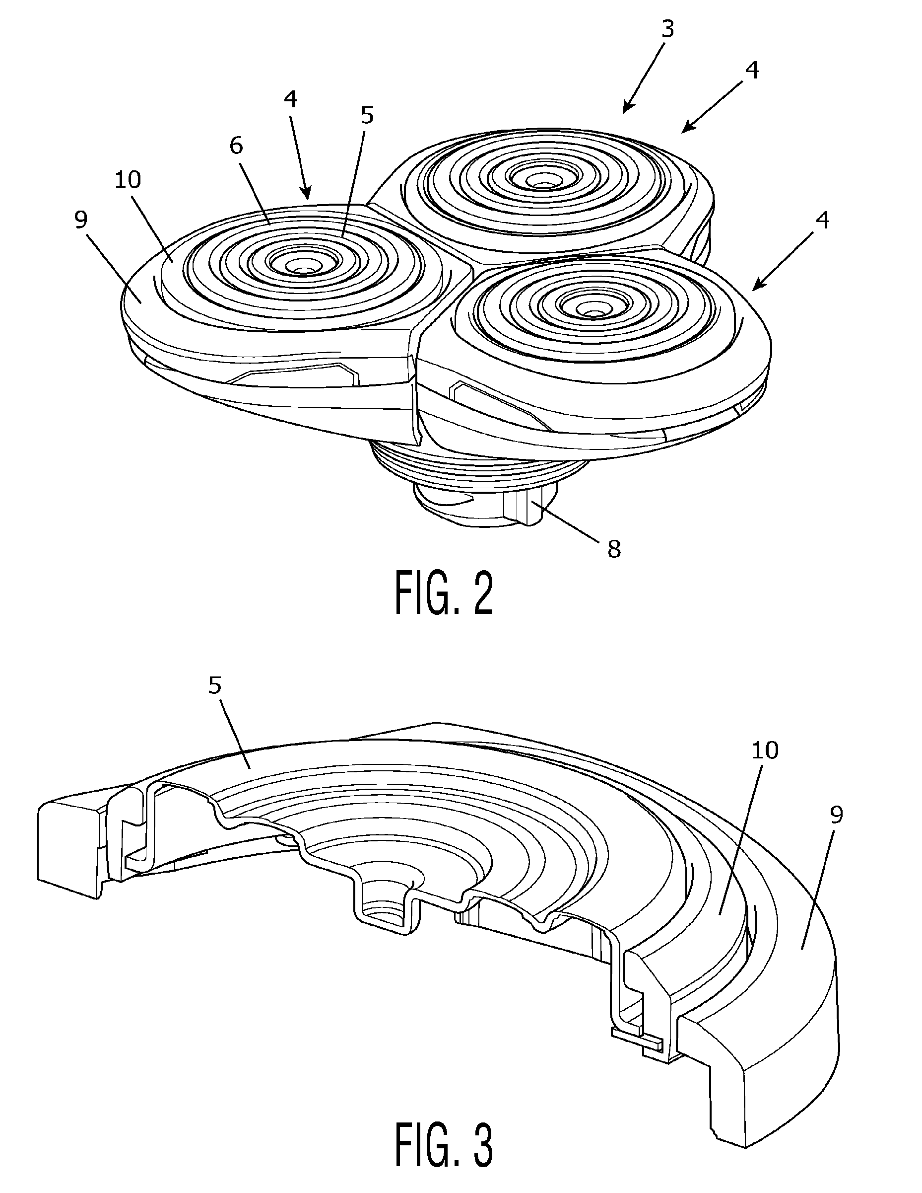
The present invention is about improving shaving results and the feel experienced by a user of the shaving device by eliminating the above-mentioned disadvantages. This is achieved by providing a shaving head with a tilting axis that is close to skin level and has a relatively smooth surface. The shaving head includes at least two suspension members connected in a concentric arrangement at two places defining the tilting axis of the suspension members with respect to each other. The suspension members may cover at least a portion of each other to improve the feel of the cutting units. The invention allows for a more uniform pressure distribution on the cutting unit and improves contour following capabilities, particularly in areas of smaller and larger curvature changes. It also allows for a situation in which necessary skin pressure for optimal shaving performance is less user-dependent and achieves better sensitivity to friction between skin and cutting unit and more uniform skin contact.

Problems solved by technology

A number of disadvantages appear to be associated with the shaving device.
In the process, it appears that a reaction on the skin involves a sliding effect, which results in frequently changing stretching and compressing of the skin.
Furthermore, there appears to be a non-uniform skin pressure distribution between skin and cutting units.
Also, it is only possible to closely follow purely convex and concave contours.

Method used


Image

  • Shaving device with improved contour following
  • Shaving device with improved contour following
  • Shaving device with improved contour following

Examples


Embodiment Construction

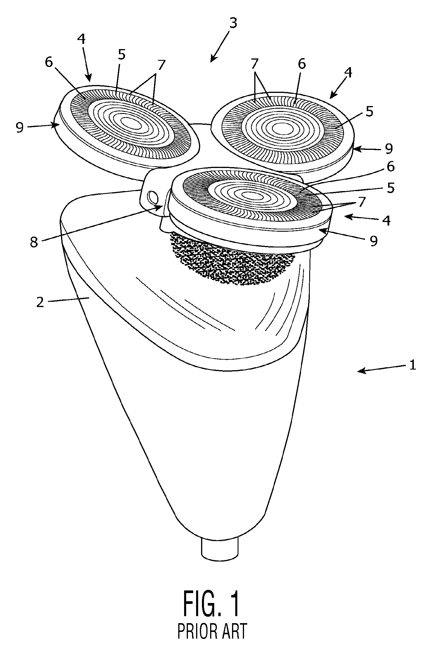
[0029]FIG. 1 shows a conventional shaving device 1 such as known from WO 2006 / 067721. The shaving device 1 is a rotary shaving device in which a shaving action is realized by using rotating components. Another well-known type of shaving device is a device in which a shaving action is realized by using reciprocating components. For the sake of completeness, it is noted that the present invention is applicable in various types of shaving devices.

[0030]The shaving device 1 comprises a body portion 2 and a shaving head 3 in which a number of cutting units 4 are located. The body portion 2 is intended to be taken hold of by a user of the shaving device 1, while the cutting units 4 are intended to be positioned against skin which is to be subjected to a shaving action, for actually performing a shaving action. In the shown example, the shaving head 3 has three cutting units 4.

[0031]Each cutting unit 4 comprises an external cutting member 5 which is shaped like a cap having an external ski...


PUM


Abstract

A shaving head includes at least one cutting unit in which an external cutting member is subjected to a shaving action. The external cutting member is suspended relative to a holder of the shaving head through suspension means. The suspension means includes at least two pivot constructions, wherein one pivot construction enables a member of the suspension means to be pivotable relative to the holder. The other pivot construction enables the external cutting member to be pivotable relative to the suspension member. Furthermore, a pivoting stiffness of a connection of the latter pivot construction is lower than a pivoting stiffness of the first pivot construction. In this manner, good contour following performance is obtained at two levels, in both relatively small and relatively large curvature changing areas.

Description

FIELD OF THE INVENTION[0001]The present invention relates to a shaving head for use in a shaving device for removing hairs from skin by cutting through the hairs, comprising at least one cutting unit, and a holder for holding the cutting unit, which holder is intended to be mounted on a body portion of the shaving device, which body portion is intended to be taken hold of by a user of the shaving device, and serves for accommodating various members of the shaving device,[0002]wherein the cutting unit comprises an external cutting member having a surface which is intended for contacting skin during a shaving action, and which is interrupted by openings for allowing hairs to pass, wherein the cutting unit further comprises an internal cutting member which is drivable for movement along the openings in the surface of the external cutting member, and which is adapted to cut through hairs during such movement,[0003]wherein the external cutting member is suspended relative to the holder t...

Claims


Application Information

Patent Timeline
Patent Type & Authority Patents(United States)
IPC IPC(8): B26B19/14
CPCB26B19/14B26B19/146B26B19/145B26B19/143
Inventor BRADA, YPESMEDINGA, OEGEBARON, SINT
Owner KONINK PHILIPS ELECTRONICS NV
Learn More