
Methods and systems for electrode placement

a technology of electrode placement and electrode placement, applied in the field of methods and systems for electrode placement, can solve the problems of difficult comparison of ecg results to standard ecg data, incorrect placement of electrodes on patients, adverse effects on ecg,

Active Publication Date: 2015-12-29
ALIVECOR
View PDF427 Cites 14 Cited by
  • Summary
  • Abstract
  • Description
  • Claims
  • Application Information

AI Technical Summary

Benefits of technology

The patent describes methods, devices, and systems for guiding the placement of electrodes on a patient for ECG measurements. The methods involve comparing a picture of the patient to a database of predetermined electrode positions for different body types. The picture may be taken using a handheld computer device or a mobile phone. The system then presents an image of the patient with the positions of the electrodes indicated. The methods may be used in a hospital or at home with a patient. The system can also normalize the picture to adjust the size and brightness of the patient's image. Overall, the methods and systems provide a convenient and accurate way to guide the placement of electrodes on a patient for ECG measurements.

Problems solved by technology

The consequences of placing the electrodes outside of the predetermined, conventional, or standard locations on the body may result in inaccurate results.
Despite the common use of ECGs within the medical profession, it is not uncommon for electrodes to be incorrectly placed on the patient by the nurse, medical technician, or physician.
Incorrect placement of electrodes can adversely affect the ECG results and make comparison of the ECG results to standard ECG data difficult.
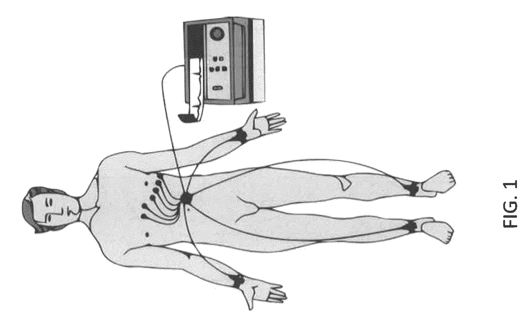
Because of this sensitivity, the placement of leads is typically left to trained medical technicians (e.g., ECG technicians), as it is difficult for an untrained user to correctly place electrodes; it would be particularly difficult for an untrained user to correctly place leads on their own body.
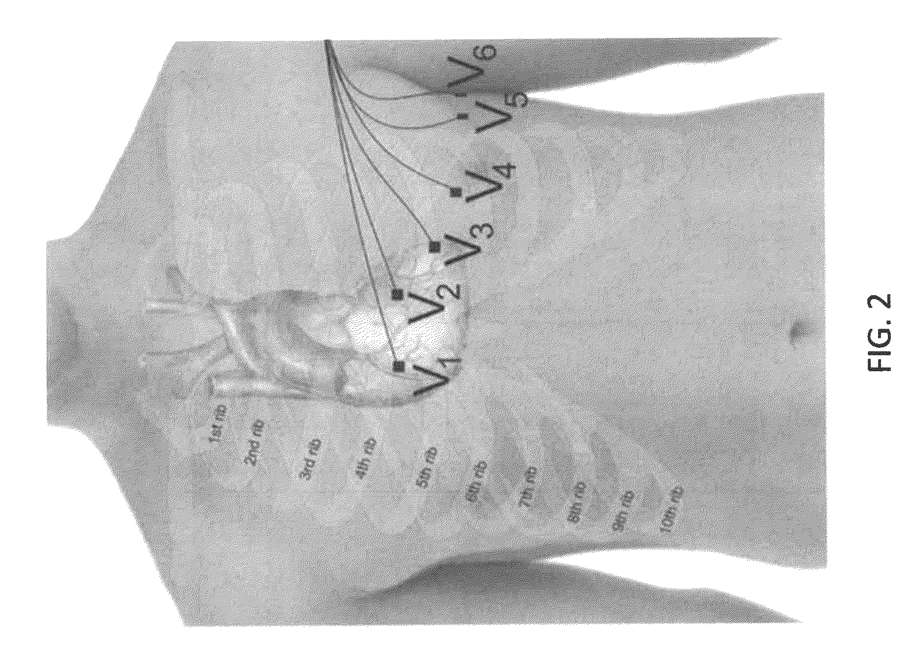
As mentioned, placing one or more of the electrodes used to measure an ECG outside of the accepted (standard or conventional) positions on the patient's body can affect the ECG, making it difficult to compare to a standard ECG and therefore difficult for a medical professional to interpret.
Electrodes are typically placed on a patient by a human, allowing an opportunity for human error to result in incorrect electrode placement.
Although attempts have been made to minimize the error introduced by varying electrode placement in ECG systems, including creating systems that are supposed to tolerate a greater variability in ECG measurement, these efforts have had limited success.
Unfortunately, U.S. Pat. No. 6,282,440 does not provide a method for guiding the initial placement of electrodes or easily correcting incorrect measurements.
The electrode positioning differences between the standard configuration and the Mason-Likar system can result in differences in the ECG signals received, since the relative positioning of the arm electrodes affects the measured leads (see, e.g., “Resting 12-Lead ECG Electrode Placement and Associated Problems” by Macfarlane et al., SCST Update 1995).

Method used


Image

  • Methods and systems for electrode placement
  • Methods and systems for electrode placement
  • Methods and systems for electrode placement

Examples


example 1

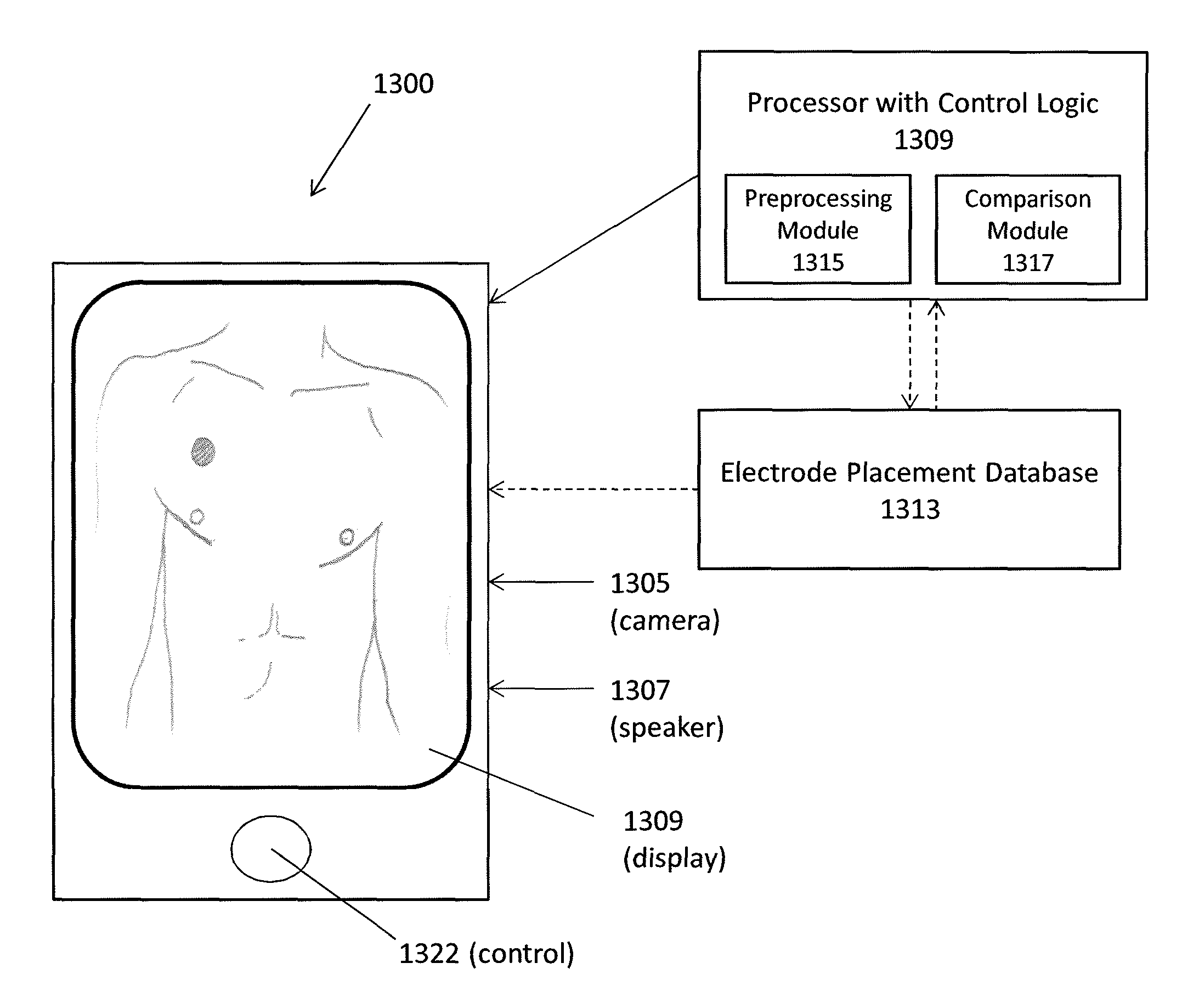
[0104]FIG. 12 is a flowchart of one exemplary method 90 for determining the placement of electrodes on a patient. A picture of a patient including a sizing marker is received 92. The picture of the patient is normalized using the sizing marker to produce a normalized picture of the patient 94. The normalized picture of the patient is compared to a database comprising representations of a plurality of body types and predetermined electrode placement positions for each body type to determine positioning of electrodes on the patient 96. An image of the patient is then presented showing positioning of electrodes on the image of the patient 98.

[0105]The image can be presented on a handheld computer device such as a smartphone or tablet computer. The user or patient can place the electrodes based on the presented image. The electrodes can then be used to take an ECG.

example 2

[0106]A smartphone can be used by an emergency medical technician (EMT) to take a picture of the chest of a patient. The picture of the patient can be selected by the EMT for use with the smartphone application. The smartphone application can then present an image of the patient showing the electrode placement on the image of the patient to the EMT. The EMT can then place electrodes on the body of the patient using the image of the patient showing the electrode placement. After placement of the electrodes the patient is ready to have an ECG taken. The ECG can be taken by the EMT or taken later.

example 3

[0107]A smartphone or tablet computer can be used by a doctor or nurse in a medical office to take a picture of the patient. The picture of the patient can be selected by the doctor or nurse for use with the smartphone or tablet computer application. The smartphone or tablet computer application can then present an image of the patient showing the electrode placement on the image of the patient to the doctor or nurse. The doctor or nurse can place electrodes on the body of the patient using the image of the patient showing the electrode placement. After placement of the electrodes the patient is ready to have an ECG taken.


PUM


Abstract

Described herein are systems, devices and methods for guiding placement of electrodes, and particularly ECG electrodes on a patient. A picture of the patient's body the patient can be analyzed to determine where on the patient's body to place electrodes according to a predetermined, conventional or standard placement pattern. The methods, devices and systems may then guide a user in positioning or correcting the position of electrodes on the patient. For example, an image of the patient may be provided showing the correct position of the electrodes, which may act as a patient-specific map or guide. The electrode placement positions can correspond to conventional or standard 12-lead ECG electrode positions.

Description

CROSS REFERENCE TO RELATED APPLICATIONS[0001]This patent application claims priority to U.S. Provisional Pat. Application No. 61 / 749,790, titled “METHODS AND SYSTEMS FOR ELECTRODE PLACEMENT,” filed on Jan. 7, 2013.[0002]This patent application may be related to U.S. Pat. application Ser. No. 13 / 964,490, titled “HEART MONITORING SYSTEM USABLE WITH A SMARTPHONE OR COMPUTER,” filed Aug. 12, 2013, which is a continuation of U.S. Pat. No. 8,509,882, titled “HEART MONITORING SYSTEM USABLE WITH A SMARTPHONE OR COMPUTER,” filed on Jun. 8, 2010, and to U.S. Pat. application Ser. No. 13 / 108,738, titled “WIRELESS, ULTRASONIC PERSONAL HEALTH MONITORING SYSTEM,” filed on May 16, 2011, and published as US-2011-0301439, each of which is herein incorporated by reference in its entirety.INCORPORATION BY REFERENCE[0003]All publications and patent applications mentioned in this specification are herein incorporated by reference to the same extent as if each individual publication or patent application...

Claims


Application Information

Patent Timeline
Patent Type & Authority Patents(United States)
IPC IPC(8): A61B5/0402A61B5/00
CPCA61B5/70A61B5/0402A61B5/318A61B5/33A61B5/684
Inventor ALBERT, DAVID E.
Owner ALIVECOR
Learn More