Tissue spreading vascular clips with locking mechanism and non-slip clamping surfaces

Active Publication Date: 2015-12-29
TYCO HEALTHCARE GRP LP
View PDF6 Cites 204 Cited by
  • Summary
  • Abstract
  • Description
  • Claims
  • Application Information

AI Technical Summary

Benefits of technology

[0020]An alternative clip design includes one arm (either a female arm or a male arm) having a pair of elongated arms or spars separated by a space or gap. The gap between the spars receives an elongated wedge-shaped ridge projecting from the clamping surface of the opposite arm, when the arms are in a closed position. The gap is wide enough to allow at least a portion of the ridge and clamped tissue or vessel to fit within the gap, thus preventing dislodgment of the clip during extreme pressure circumstances. In another embodiment, one arm includes a central window.
[0021]An exemplary clip includes a plurality of bosses, including a hinge boss, for gripping by an applicator and stabilizing during use. As used herein, a boss is a projection or protuberance that can be engaged by an applicator. The hinge boss is a grippable boss (i.e., a protrusion suitable for gripping) at or near the hinge. Gripping the hinge boss during use prevents undesirable angula

Problems solved by technology

Suturing requires complex manipulations of the needle and suture material to form the knots required to secure the vessel.
Such complex manipulations are time-consuming and difficult to perform, particularly in endoscopic surgical procedures, which are characterized by limited space and visibility.
However, metal clips, which are radio-opaque, interfere with x-ray imaging.
Accurate planing and windowing manipulations are time-consuming and difficult to perform, particularly in endoscopic surgical procedures, which are characterized by limited space and visibility.
Furthermore, creating window

Method used


Image

  • Tissue spreading vascular clips with locking mechanism and non-slip clamping surfaces
  • Tissue spreading vascular clips with locking mechanism and non-slip clamping surfaces
  • Tissue spreading vascular clips with locking mechanism and non-slip clamping surfaces

Examples


Embodiment Construction

Surgical Clip with Head Locking Capability and a Hinge Portion Locking

[0065]In this embodiment, a ligating clip has a head locking capability and a hinge portion locking capability.

Hinge Lock

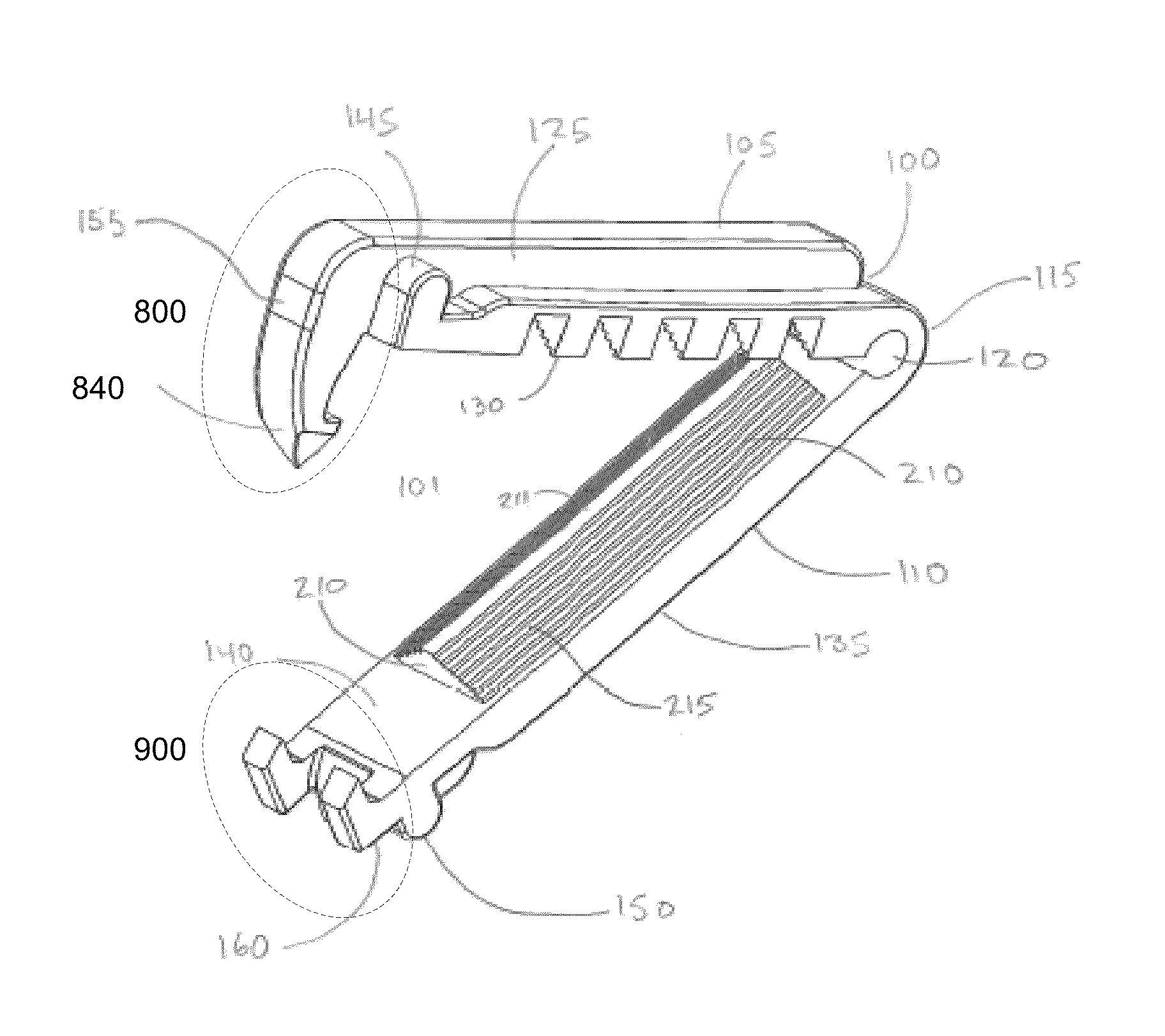
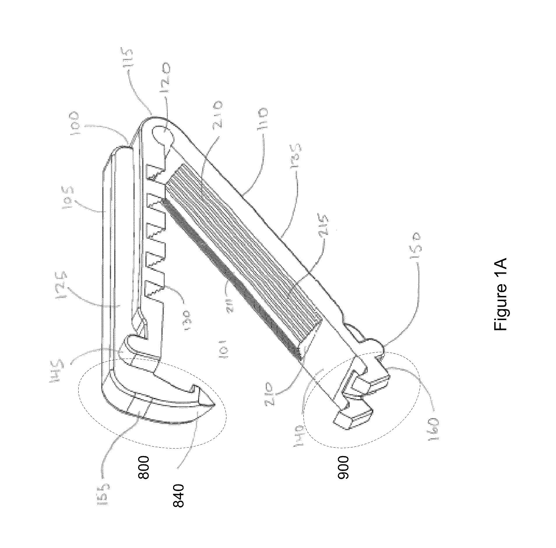
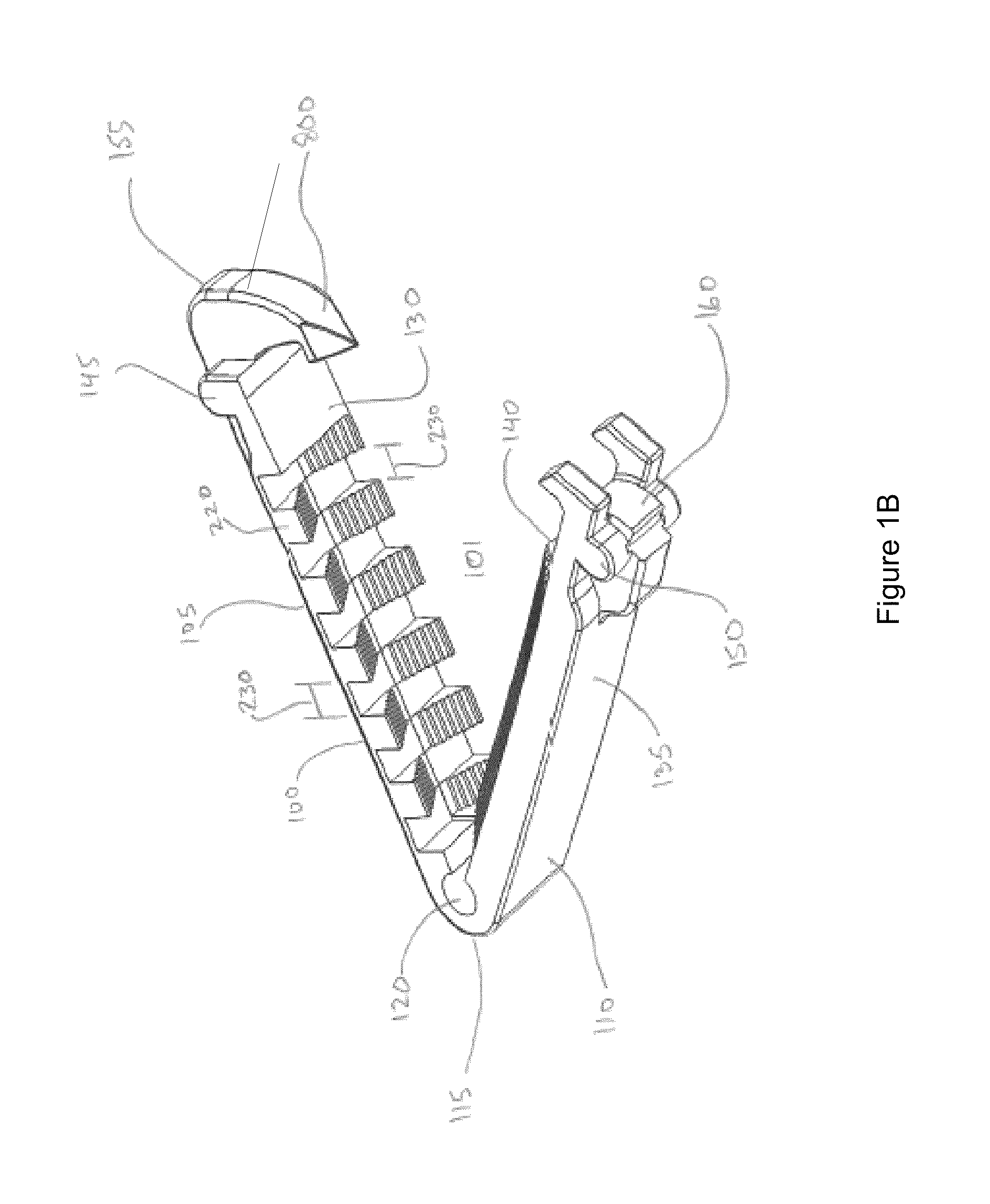
[0066]In FIG. 8F-8H, the hinge portion 115 of a surgical clip is constructed with a hinge lock 812 comprising a first hinge locking element 810 and a second hinge locking element 820, thus providing an irreversible locking mechanism at the proximal hinge end 115 of the clip 100. As the clip arms 105, 110 are re-approximated together to clamp tissue between the arms, a prong 815 of first hinge locking element 810 will fit irreversibly into a slot or groove 825 of the second hinge locking element 820. Once the prong 815 and slot 825 are united, the hinge 115 is said to be in the locked and closed position. By having a hinge lock apparatus at the hinge area, there will be constant pressure applied to the tissue being clamped at the hinge region as well as the male-female locking interface region—a ...


PUM


Abstract

A surgical clip includes a pair of opposed arms joined at one end by an integrally formed flexible hinge and a hinge lock. A male head element near the free end of one arm is configured to spread tissue when the male head element is urged towards a head mating element near the end of the opposite arm. The clamping side of an arm may include a protruding feature, such as a wedge shape elongated ridge, while the clamping side of the opposite arm includes a corresponding trough or aperture that receives the protruding feature. Clamping surfaces may include non-slip protrusions, such as ribs, ridges, cones or pins. An applicator holding feature, such as a boss, near the hinge prevents the clip from yawing and becoming askew during application.

Description

RELATED APPLICATIONS[0001]This non-provisional US patent application is related to U.S. Provisional Application No. 61 / 713,597 filed on Oct. 14, 2012, and claims the benefit of that filing date.FIELD OF THE INVENTION[0002]The present invention relates to surgical clips, and, more particularly, to a biocompatible surgical clip with grooved clamping surfaces to prevent slipping, a tissue penetrating head lock mechanism, and a locking hinge portion to provide greater tension and security when clamping tissue between the two arms of the clip.BACKGROUND[0003]A wide number of surgical procedures employ surgical clips (i.e., ligation clips). Such surgical procedures may require vessels, organs or other tissues of the human body to be ligated. Surgical clips ligate, clamp, close off or otherwise occlude the engaged portion of the clamped vessels, organs or other tissues in a surgical site. Such clips may also be used to secure the ends of a suture, as in place of a conventional suture knot....

Claims


Application Information

Patent Timeline
IPC IPC(8): A61B17/08A61B17/122A61B17/128A61B17/064A61B17/00
CPCA61B17/1227A61B17/083A61B17/064A61B17/1285A61B2017/0645A61B2017/00858A61B17/122
Inventor PATEL, MANOJ B.PATEL, BHAILAL H.ALBALA, DAVID M.
Owner TYCO HEALTHCARE GRP LP
Why Eureka
Try Eureka