
Rectifying-and-modulating circuit and wireless power receiver incorporating the same

a technology of rectifying and modulating circuits and wireless power receivers, applied in the direction of electric variable regulation, process and machine control, instruments, etc., can solve the problems of occupying a relatively large area and high cost of conventional wireless power receivers

Active Publication Date: 2015-12-29
RICHTEK TECH
View PDF2 Cites 246 Cited by
  • Summary
  • Abstract
  • Description
  • Claims
  • Application Information

AI Technical Summary

Benefits of technology

This patent invention is a rectifying-and-modulating circuit for a wireless power receiver. The circuit includes switches and a control unit that work together to rectify the induced current from a wireless power transmitter. The switches can be controlled to change the amplitude of the induced current. The circuit is designed to overcome the limitations of previous designs that resulted in reduced efficiency and limited control over the induced current. Therefore, the technical effect of this invention is to provide a more efficient and controllable rectifying-and-modulating circuit for wireless power receivers.

Problems solved by technology

In this case, the conventional wireless power receiver has a relatively high cost and occupies a relatively large area.

Method used


Image

  • Rectifying-and-modulating circuit and wireless power receiver incorporating the same
  • Rectifying-and-modulating circuit and wireless power receiver incorporating the same
  • Rectifying-and-modulating circuit and wireless power receiver incorporating the same

Examples


Embodiment Construction

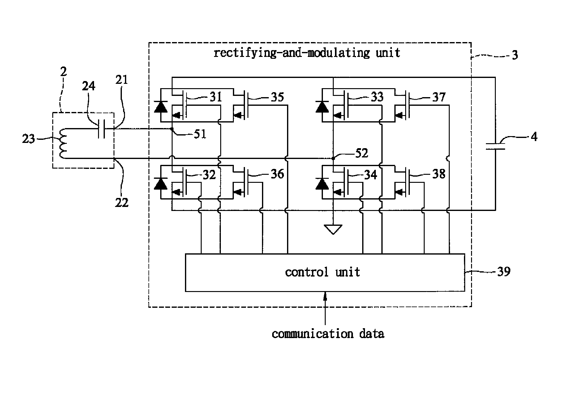
[0016]Referring to FIG. 3, the preferred embodiment of a wireless power receiver according to this invention is configured to cooperate with a wireless power transmitter (not shown) to achieve power transfer and data communication. The wireless power receiver of this embodiment includes a power receiving circuit 2, a rectifying-and-modulating circuit 3, and a filtering capacitor 4.

[0017]The power receiving circuit 2 has first and second terminals 21, 22, and is configured to wirelessly receive power transmitted from the wireless power transmitter so as to generate an induced current flowing through the first and second terminals 21, 22. In this embodiment, the power receiving circuit 2 includes a series connection of a coil 23 and a capacitor 24 coupled between the first and second terminals 21, 22.

[0018]The rectifying-and-modulating circuit 3 includes a series connection of first and second switches 31, 32, a series connection of third and fourth switches 33, 34, fifth to eighth sw...


PUM


Abstract

A wireless power receiver includes a power receiving circuit wirelessly receiving power transmitted from a wireless power transmitter so as to generate an induced current, and a rectifying-and-modulating circuit including first to eighth switches and a control unit. The control unit is operable to control operation of each of the first to eighth switches between conduction and non-conduction. Accordingly, the first to fourth switches cooperatively constitute a full-bridge rectifier for rectifying the induced current generated by the power receiving circuit, and each of the fifth to eighth switches is operable to switch synchronously with a respective one of the first to fourth switches or to became non-conducting, thereby changing an amplitude of the induced current.

Description

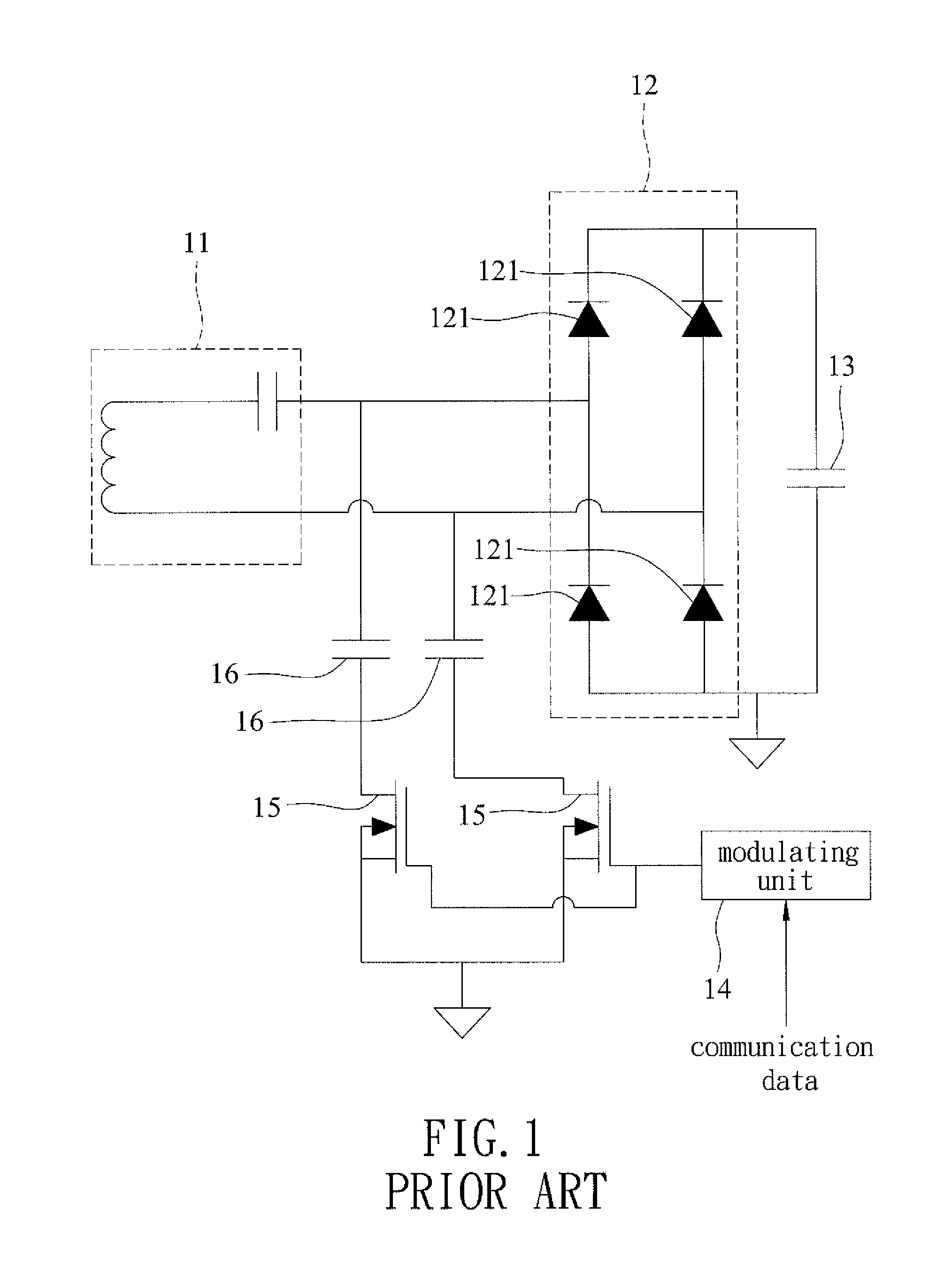
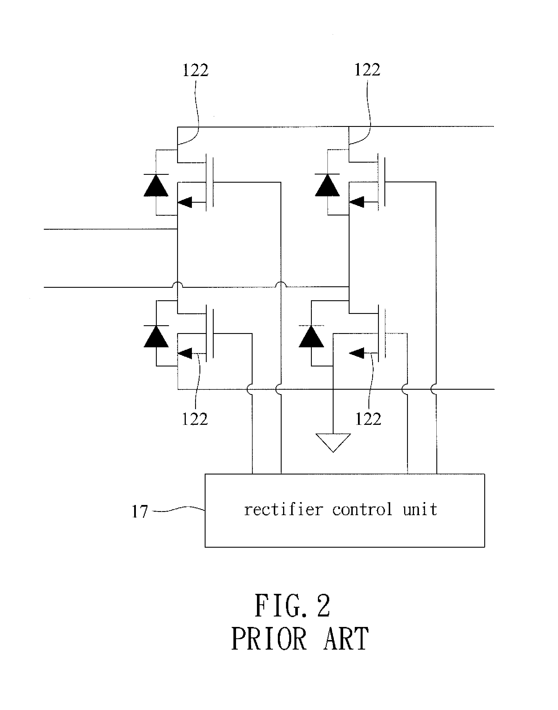
CROSS-REFERENCE TO RELATED APPLICATION[0001]This application claims priority of Taiwanese Application No. 102117020, filed on May. 14, 2013, the contents of which are hereby incorporated by reference.BACKGROUND OF THE INVENTION[0002]1. Field of the Invention[0003]This invention relates to a wireless power receiver, and more particularly to a rectifying-and-modulating circuit and a wireless power receiver incorporating the same.[0004]2. Description of the Related Art[0005]Referring to FIG. 1, a conventional wireless power receiver can cooperate with a wireless power transmitter (not shown) to achieve power transfer and data communication. The conventional wireless power receiver includes a power receiving circuit 11, a full-bridge rectifier 12, a filtering capacitor 13, a modulating unit 14, two switches 15, and two modulating capacitors 16. The power receiving circuit 11 is used to wirelessly receive power transmitted from the wireless power transmitter so as to generate an induced ...

Claims


Application Information

Patent Timeline
Patent Type & Authority Patents(United States)
IPC IPC(8): H03C1/54H02J7/02H02M1/42H02M5/45G06F1/32H02M3/335H02M5/458H02M3/158
CPCH02J7/025G06F1/3293H02M3/1588H02M2001/4275H02M5/4505H02M5/4585H02M3/33592H02J50/12H02J50/80H02M1/4275
Inventor HUANG, WEI-JENHUANG, TSUNG-WEILIN, SHUI-MU
Owner RICHTEK TECH
Learn More