Method for operating a braking system and a corresponding control unit

a technology of braking system and control unit, which is applied in the direction of braking system, analogue processes for specific applications, instruments, etc., can solve the problems of both phases being perceived as uncomfortable by the driver of the vehicle and and achieve the effect of increasing the comfort of the occupants of the vehicl

Active Publication Date: 2016-01-05
ROBERT BOSCH GMBH
View PDF22 Cites 2 Cited by
  • Summary
  • Abstract
  • Description
  • Claims
  • Application Information

AI Technical Summary

Benefits of technology

[0007]The method having the features described herein is believed to have the advantage over the related art that no additional sensors for determining the reference speed are required, i.e., the traveling comfort for the occupants of the vehicle is increased. This may be achieved according to the exemplary embodiments and / or exemplary methods of the present invention in that the braking force variable is subsequently set to a setpoint braking force variable, which corresponds to a selectable portion of the braking force variable present at the recognition of the locking tendency, for a certain time period. After the braking force variable has been reduced to the certain value, it should thus be set to the setpoint braking force variable. For this purpose, the braking force variable present at the recognition of the locking tendency is stored. The setpoint braking force variable corresponds to a selectable portion of this braking force variable. The setpoint braking force variable is set at the braking device for the certain time period in a controlling and / or regulating manner.
[0009]Here, it is common to carry out the setting of the braking force variable not too infrequently and not concurrently, i.e., alternatingly. If, however, the setting is carried out alternatingly for the wheels of one axle of the vehicle, strong cyclic braking force variable differences between the wheels of the axle (alternating phase) occur at a road surface beneath the vehicle, which has a certain μ slip characteristic (a very pointed shape of the μ-slip curve maximum). In a concurrent phase, however, strong oscillations of the braking force variable occur. Both phases alike are perceived as uncomfortable by the driver of the vehicle and the occupants of the vehicle. With the aid of the method according to the present invention, such oscillations in the braking force variable or the braking force variable differences may be reduced, the braking power of the wheel or the vehicle being possible at the same time and it being possible to reliably determine the reference velocity of the vehicle. The cycle for setting the braking force variable of the wheel is supplemented with the step in which the setpoint braking force variable is set at the braking device for the certain time period.
[0010]This means that the braking force variable is initially increased until the locking tendency is recognized and then reduced to the certain value and the braking force variable is subsequently set to the setpoint braking force variable. Subsequently, a new cycle starts, i.e., the braking force variable is again increased until the locking tendency is recognized. In this way, an “oscillating” change of the braking force variable is at least interrupted by holding the braking force variable for the certain time period so that no oscillations of the wheel or the axle are excited. By holding the braking force variable at the setpoint braking force variable the braking power does not decrease. To the contrary, the mean braking power of the vehicle is even increased in the normal case. Likewise, the determination of the reference speed may be simplified by the controlled and / or regulated holding phase at the setpoint braking force variable.
[0011]One refinement of the present invention provides that the vehicle has at least two brake-able wheels, in particular provided on a common axle. The method is particularly advantageously applicable when multiple wheels are present. These wheels may, for example, be present on the common axle. In such a vehicle design, the braking forces, which are applied with the aid of the braking device to the brake-able wheels, may be synchronized with one another so that the traveling comfort of the vehicle is further increased.
[0013]As soon as the calibration phase for the one wheel is completed, the holding phase is carried out for this wheel, while the calibration phase starts for the other wheel. Oscillations of the braking force variable between the wheels are thus reduced, thus significantly increasing the traveling comfort of the vehicle. Due to the holding phase, the frequency is reduced at which the braking force variable is set. This results in a reduction of the volumetric flow-rate of the brake fluid since it is usually discharged under pressure reduction from the braking device into a reservoir when the braking force variable is reduced. The brake fluid must subsequently be delivered by a pump (feedback pump) from the reservoir back into a main brake cylinder of the braking system. Reducing the frequency or reducing the volumetric flow-rate results in a smaller movement of the brake pedal (increased pedal comfort). Furthermore, the pump speed with which the brake fluid is delivered from the reservoir to the main brake cylinder may be reduced (less noise production) or even a smaller and thus less expensive pump, in particular pump motor, may be provided.
[0021]One refinement of the present invention provides that the time period is selected according to a desired lateral cornering force of the vehicle and / or is selected to be smaller in the case of a reduced locking tendency. By extending the time period, the lateral cornering force of the vehicle may be increased. It may thus be reasonable to extend the time period during certain driving states of the vehicle, e.g., when negotiating curves with the vehicle. The setting or selecting of the time period may be provided starting from a driver assistance device. As soon as it determines that the increase in the lateral cornering force is desired or necessary, it may adapt the time period accordingly. It is likewise possible to increase the braking power of the wheel or the vehicle by selecting the time period to be smaller if a reduced locking tendency of the wheel is determined. Thus, the braking force variable of the wheel may be quickly adapted to the increasing friction values between the road surface and the wheel. The time period may certainly also be selected as a function of a locking tendency of other wheels of the motor vehicle.

Problems solved by technology

Both phases alike are perceived as uncomfortable by the driver of the vehicle and the occupants of the vehicle.

Method used


Image

  • Method for operating a braking system and a corresponding control unit
  • Method for operating a braking system and a corresponding control unit

Examples


Embodiment Construction

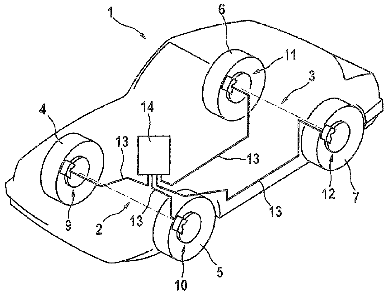
[0027]FIG. 1 shows a schematic view of a vehicle 1. The vehicle has two axles 2 and 3, each of axles 2 and 3 having wheels 4 and 5 and 6 and 7, respectively. Vehicle 1 has a braking system 8 which includes braking devices 9, 10, 11, and 12, each associated with wheels 4, 5, 6, and 7, respectively. These wheels are connected to a control and / or regulating unit 14 via lines 13. Control and regulating unit 14 may apply a braking force variable, which represents a braking force, to each of wheels 4 through 7, a brake pressure p being built up for this purpose in each of braking devices 9 through 12.

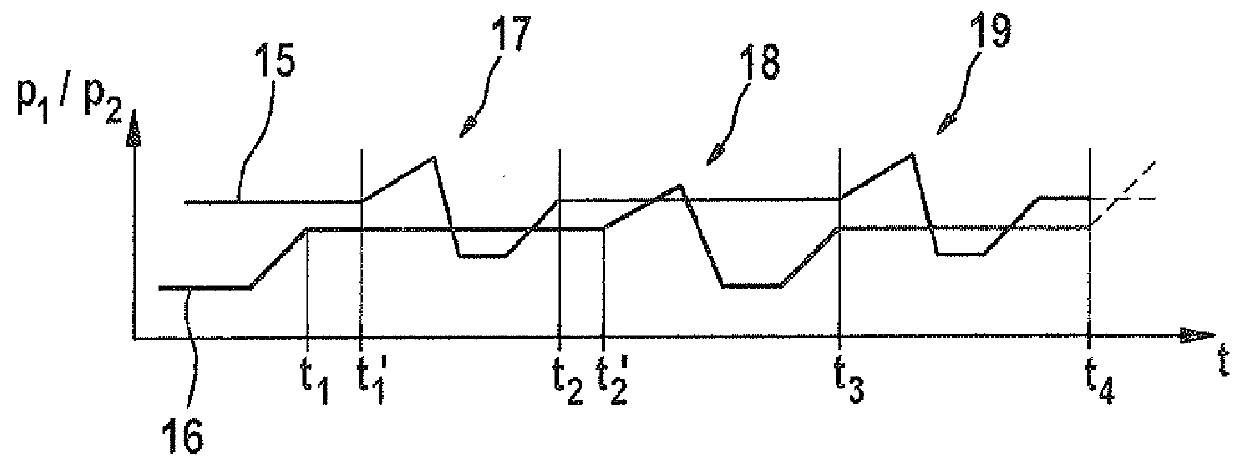
[0028]FIG. 2 shows a diagram in which brake pressures p1 and p2 are plotted against time t. Brake pressures p1 and p2 are associated with wheels 4 and 5 of axle 2, by way of example. A first curve 15 shows brake pressure p1 of wheel 4 of a vehicle 1. Accordingly, a second curve 2 shows brake pressure p2 of wheel 6 of vehicle 1, both wheels 4 and 5 being provided on common axle 2 and being bra...


PUM


Abstract

A method for operating a braking system of a vehicle having at least one brake-able wheel, a braking force variable, which represents a braking force, of a braking device associated with the wheel being increased during a braking operation until a locking tendency of the wheel is recognized, and then reduced to a certain value. It is provided that the braking force variable is subsequently set to a setpoint braking force variable, which corresponds to a selectable portion of the braking force variable present at the recognition of the locking tendency, for a certain time period. Also described is a control unit for implementing the method.

Description

THE FIELD OF THE INVENTION[0001]The present invention relates to a method for operating a braking system of a vehicle having at least one brake-able wheel, a braking force variable, which represents a braking force, of a braking device associated with a wheel being increased during a braking operation until a locking tendency of the wheel is recognized, and then reduced again to a certain value. The present invention furthermore relates to a corresponding control unit.BACKGROUND INFORMATION[0002]Methods of the type mentioned at the outset are believed to be understood from the related art. These methods are supposed to prevent the wheel from locking on a road surface beneath the vehicle in such a way that the wheel slip exceeds a certain value starting from which the locking tendency occurs. In this way, it should be prevented that the wheel gets too far into the sliding friction range, on the one hand, and the vehicle should remain controllable, on the other hand. The latter is not...

Claims


Application Information

Patent Timeline
Patent Type & Authority Patents(United States)
IPC IPC(8): G06F7/70G06G7/76G06G7/00G06F19/00B60T8/1763B60T8/1755B60T8/1761B60T8/1764
CPCB60T8/17636B60T8/17555B60T8/17616B60T8/1761B60T8/1764
Inventor STREHLE, ALFREDDIEHLE, STEFANEISELE, ACHIM
Owner ROBERT BOSCH GMBH
Why Eureka
Try Eureka