Pilf resistant packaging system

a packaging system and anti-theft technology, applied in the direction of burglar alarm mechanical actuation, instruments, electric signalling details, etc., can solve the problems of difficult cutting through clear packaging, difficult packaging opening for legitimate customers, and huge problem of theft of various products within a stor

Active Publication Date: 2016-01-05
MARTINO MARC G
View PDF9 Cites 7 Cited by
  • Summary
  • Abstract
  • Description
  • Claims
  • Application Information

AI Technical Summary

Problems solved by technology

Theft of various products from within a store is a huge problem.
A thief will literally cut a product out of the clear plastic packaging and steal the product after discarding the packaging.
The prior art has focuses at making cutting through the clear packaging more difficult such that it is a deterrent to a potential thief.
However, adding a deterrent also makes the packaging harder to open for a legitimate customer.
Also, various deterrents can appear ugly and deter a customer from purchasing the product.
A problem exists when a resident wants to install shelving or other various features into a dry walled wall.
However, drywall is not nearly as strong as screwing directly into the studs of the home.
Many times during shelving installation the drywall is damaged or destroyed.
This may occur from missing the studs when attempting to screw therein, marring the drywall with improper screws, having screws become jammed or having the threads on the screw head strip.
Damage is also likely when electrical features are installed.

Method used


Image

  • Pilf resistant packaging system
  • Pilf resistant packaging system
  • Pilf resistant packaging system

Examples


Embodiment Construction

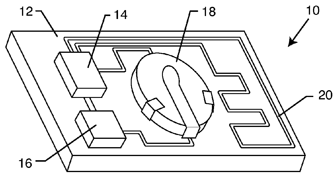
[0039]FIG. 1 is a perspective view of an exemplary embodiment of the present invention. FIG. 1 shows a pressure sensor assembly 10. The pressure sensor assembly 10 is preferably small in size such that it can be placed within a packaging of a product. Many types of pressure sensor assemblies 10 may be used by one skilled in the art. A pressure sensor assembly 10 usually has a base substrate or circuit board 12. On the base substrate / circuit board 12 is mounted a power source 18, which can be a battery 18 or an externally powered passive RFID tag / receiver 18. As shown herein it is a battery 18. A battery 18 is preferred as it can transmit an extended distance as compared to a passive RFID tag and it also doesn't require a constant external signal to derive its power.

[0040]The battery 18 is connected to a microprocessor 16. The microprocessor 16 is able to perform various tasks that it is programmed to do. However, a microprocessor 16 is not even necessary in the present invention. A ...


PUM


Abstract

A theft-proof packaging system includes a product package having a compartment configured to encapsulate a product, wherein the compartment is pneumatically pressurized above a surrounding environment. A pressure sensor assembly is located within the compartment. The pressure sensor assembly includes a pressure sensor, a power source electrically connected to the pressure sensor and a transmitter electrically connected to the power source. The transmitter is configured to send a signal. A receiving unit is located outside the compartment of the product package and disposed remote from the product package. The receiving unit includes a receiver configured to receive the signal from the transmitter and an alarm electrically coupled to the receiver. The pressure sensor assembly is configured to detect a change in pressure inside the compartment and then send the signal to the receiving unit activating the alarm.

Description

CROSS-REFERENCE TO RELATED APPLICATIONS[0001]This application claims priority to provisional application 61 / 786,597 filed on Mar. 15, 2013, the contents of which are fully incorporated herein with this statement.DESCRIPTION[0002]1. Field of the Invention[0003]The present invention generally relates to a pilf / theft resistant packaging system.[0004]2. Background of the Invention[0005]The present invention discloses two inventions, the first being directed to a pilf / theft resistant packaging system and the second being directed to a modular wall panel system.[0006]The first invention concerns pilf resistant packaging and systems thereof. Theft of various products from within a store is a huge problem. A thief will literally cut a product out of the clear plastic packaging and steal the product after discarding the packaging. For instance, some department stores claim they have four knives stolen for every one knife that they actually sell. In the prior art, many have attempted to reduc...

Claims


Application Information

Patent Timeline
Patent Type & Authority Patents(United States)
IPC IPC(8): G08B13/14B65D25/00B65D73/00E04B2/74E04F13/08G08B13/20G08B1/08G08B13/00H01H35/34B65D85/00B65B25/06G08B23/00
CPCB65D25/00B65D73/0014E04B2/7457E04F13/083G08B13/20B65D2203/10B65D2211/00E04B2002/7466E04B2002/7483E04B2002/7487H01H35/346
Inventor MARTINO, MARC, G.
Owner MARTINO MARC G
Why Eureka
Try Eureka