Method and systems for a leakage passageway of a fuel injector

a technology of fuel injector and leakage passageway, which is applied in the direction of fuel injection with fuel accumulator, fuel injection apparatus, charge feed system, etc., can solve the problems of reducing and the pressure fluctuations of the fuel rail during engine operation, so as to reduce the degradation of the common fuel rail system components. , the effect of reducing the pressure fluctuation of the fuel rail

Active Publication Date: 2016-01-12
GE GLOBAL SOURCING LLC
View PDF6 Cites 46 Cited by
  • Summary
  • Abstract
  • Description
  • Claims
  • Application Information

AI Technical Summary

Benefits of technology

[0004]In this way, the leakage passageway provides fluid communication between the injector accumulator and the common fuel rail. As a result, the total common rail fuel volume increases, thereby decreasing fuel rail pressure fluctuations during engine operation. As a result, degradation of the common fuel rail system components may decrease.

Problems solved by technology

As a result, degradation of the common fuel rail system components may decrease.

Method used


Image

  • Method and systems for a leakage passageway of a fuel injector
  • Method and systems for a leakage passageway of a fuel injector
  • Method and systems for a leakage passageway of a fuel injector

Examples


Embodiment Construction

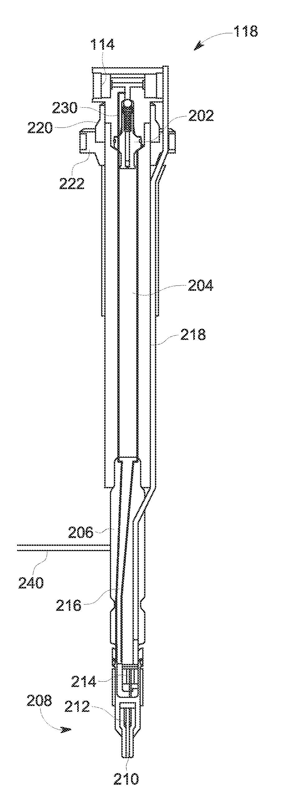
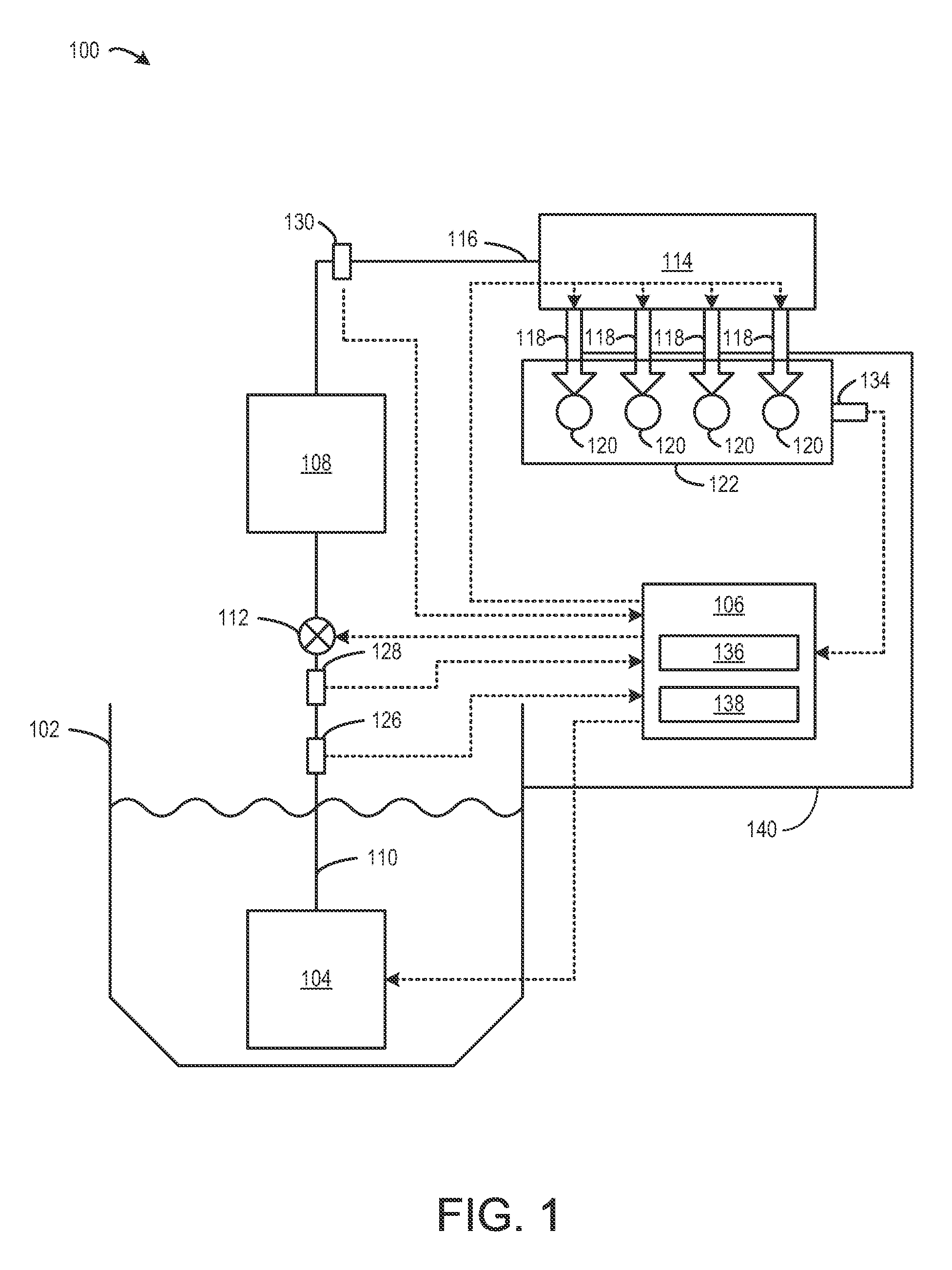
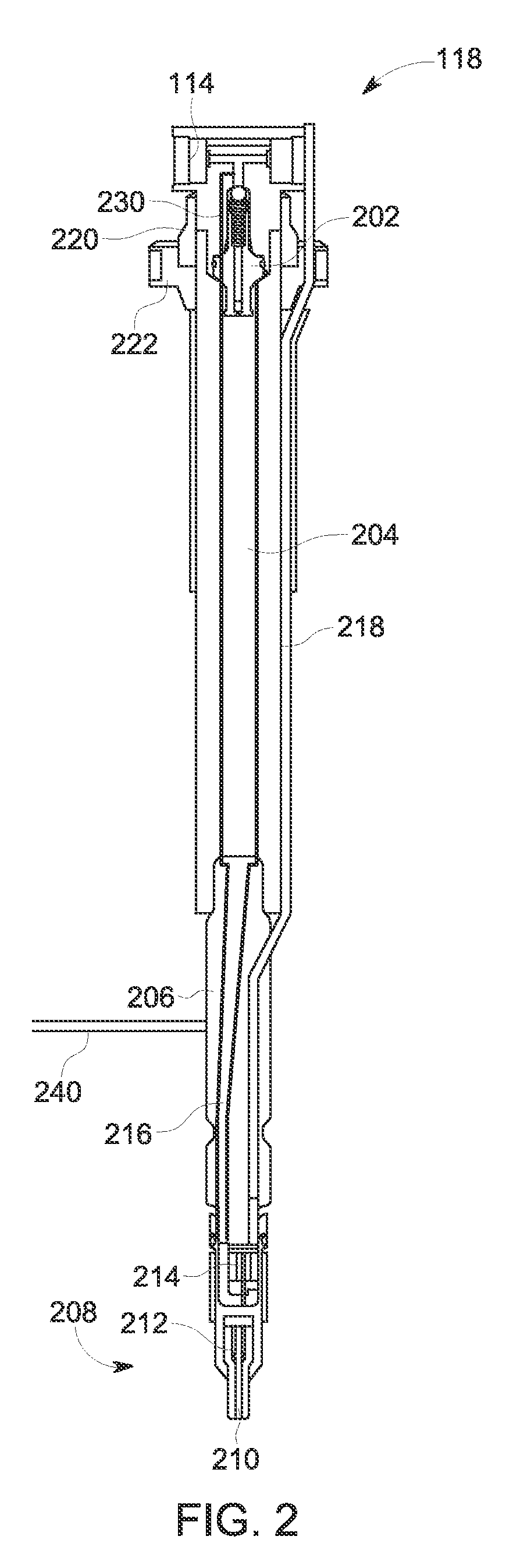
[0013]The following description relates to various embodiments of a leakage passageway for a fuel injector of a common rail fuel system. An example common rail fuel system including a common fuel rail and a plurality of fuel injectors is shown at FIG. 1. FIGS. 2-3 show an example fuel injector included in the common fuel rail system. Each fuel injector has an associated injector flow limiter valve, an injector accumulator, an injector body, and a nozzle. The injector flow limiter valve may reduce over fueling by closing during non-injection invents, thereby cutting off fluid communication between the injector accumulator and the common fuel rail. Example positions of one type of injector flow limiter valve are shown in FIG. 6. In one example, as shown at FIG. 3, a leakage passageway is coupled between an inlet of the injector flow limiter valve and the injector accumulator. As such, even during non-injection events, the injector accumulator is in fluid communication with the common ...


PUM


Abstract

Various methods and systems are provided for a leakage passageway for a fuel injector of a common rail fuel system. In one embodiment, a fuel injector for an engine comprises an injector accumulator, an injector flow limiter valve configured to control a flow of fuel from a common fuel rail and into the injector accumulator, and a leakage passageway coupled between the injector accumulator and an inlet of the injector flow limiter valve, the leakage passageway bypassing the injector flow limiter valve.

Description

FIELD[0001]Embodiments of the subject matter disclosed herein relate to methods and systems for fuel injectors of a common rail fuel system in an engine.BACKGROUND[0002]In some vehicles, fuel is provided to a diesel engine by a common rail fuel system. In the common fuel rail system, fuel injectors inject fuel from the common fuel rail to cylinders of the engine for combustion. In some examples, the common fuel rail system may include a large accumulator coupled to all the fuel injectors. In other examples, each fuel injector may have a smaller injector accumulator. Further, fuel flowing to each fuel injector may be regulated by a flow limiter valve to reduce over-fueling. During an injection event at one fuel injector, the flow limiter valves corresponding to the other fuel injectors may be closed, thereby closing off the fuel volume of the non-injecting fuel injectors from the common fuel rail. As a result, the total common rail fuel volume may be reduced, thereby resulting in lar...

Claims


Application Information

Patent Timeline
Patent Type & Authority Patents(United States)
IPC IPC(8): F02M55/00F02M55/02F02M63/00
CPCF02M55/002F02M55/025F02M63/0054F02M2200/31F02M2200/40
Inventor DAS, SUMIT KUMARNISTLER, PAUL GERARDRIVERA, JAVIERANANDHAN, MUTHU
Owner GE GLOBAL SOURCING LLC
Why Eureka
Try Eureka