Cooking hob with rotary driving means and cooking vessel usable with said hob

a technology of rotary driving means and cooking hob, which is applied in the field of cooking hob, can solve the problems of rinsing the culinary preparation inside the vessel, scratching the support plate, and the smooth and cleared surface offers very little resistance to the rotation of the vessel

Inactive Publication Date: 2016-01-19
ELECTRODOMESTICOS TAURUS
View PDF149 Cites 72 Cited by
  • Summary
  • Abstract
  • Description
  • Claims
  • Application Information

AI Technical Summary

Benefits of technology

[0008]According to a first aspect, the present invention contributes to mitigating the aforementioned and other drawbacks providing a cooking hob with rotary driving means, comprising a support plate which has a treatment area capable of supporting a cooking vessel provided with rotary blades or paddles connected to an upper magnetic coupling member, a lower magnetic coupling member rotatably assembled below the support plate, and a drive actuator operatively connected for rotating said lower magnetic coupling member and magnetically transmitting torque to said upper magnetic coupling member of said cooking vessel.
[0010]The magnetic attractive force between the lower and upper magnetic elements combined with the distance from them to the respective rotating shafts of the lower and upper magnetic coupling members creates a resistant torque which prevents the cooking vessel from rotating on the treatment area of the support plate due to a driving torque produced by the rotation of the lower coupling member when for any reason the rotary blades encounter resistance to rotation or are locked inside the cooking vessel, for example due to the conditions of the food which is being processed, provided that the driving torque does not exceed the resistant torque.
[0022]According to that described above, the magnetic attractive force between the lower and upper magnetic elements combined with the distance from them to the respective rotating shafts of the lower and upper magnetic coupling members contributes to preventing the cooking vessel from rotating on the treatment area of the support plate.

Problems solved by technology

A drawback of these cooking hobs equipped with a substantially smooth support plate and driving means to rotate a lower magnetic element and thereby establish magnetic coupling through the support plate is that if for any reason the rotary blades or paddles increase resistance to rotation or are locked inside the vessel, for example due to the conditions of the food being processed, then the entire vessel tends to rotate on the support plate being pushed by the driving means with the risk of ruining the culinary preparation inside the vessel, scratching the support plate or even causing an accident.
Nevertheless, this smooth and cleared surface offers very little resistance to the rotation of the vessel.

Method used


Image

  • Cooking hob with rotary driving means and cooking vessel usable with said hob
  • Cooking hob with rotary driving means and cooking vessel usable with said hob
  • Cooking hob with rotary driving means and cooking vessel usable with said hob

Examples


Embodiment Construction

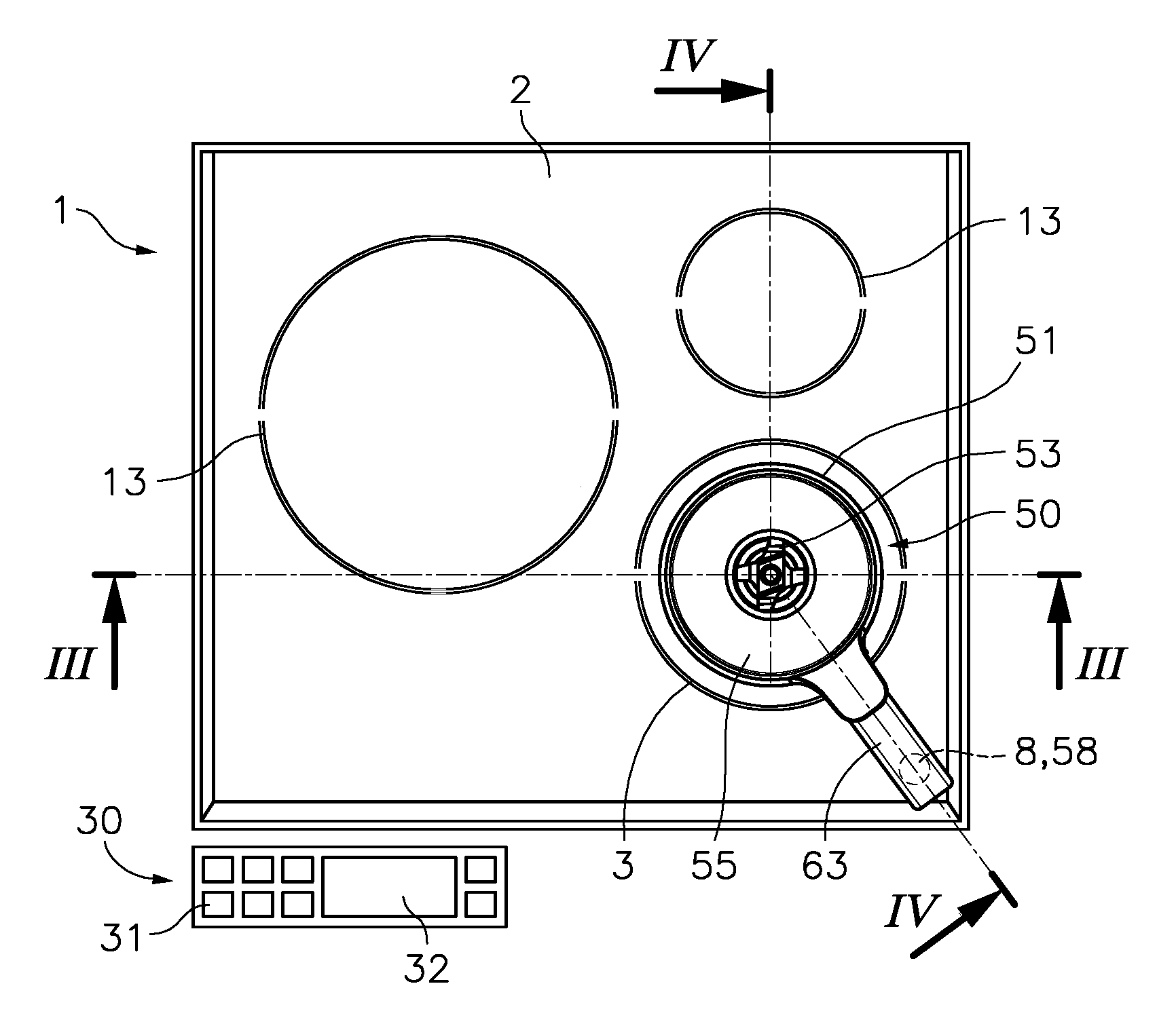
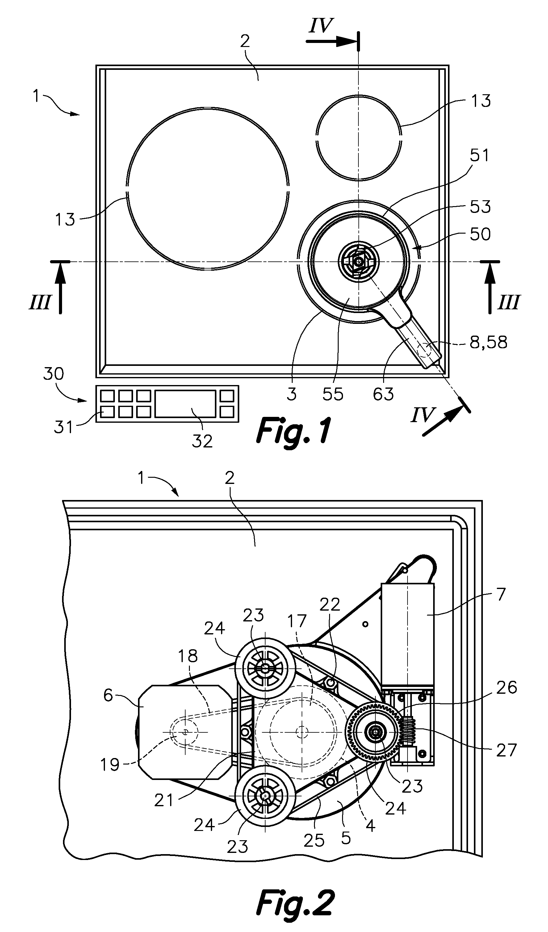
[0036]Referring first to FIG. 1, reference number 1 generally designates a cooking hob with rotary driving means according to an embodiment of a first aspect of the present invention and reference number 50 generally designates a cooking vessel provided with rotary blades or paddles according to an embodiment of a second aspect of the present invention. The cooking hob 1 comprises a continuous support plate 2, made of glass, glass ceramic or the like, which has several cooking areas 13 and a treatment area 3 all of them indicated graphically. The cooking areas 13 are conventionally associated with respective heating means (not shown) located below the support plate 2.

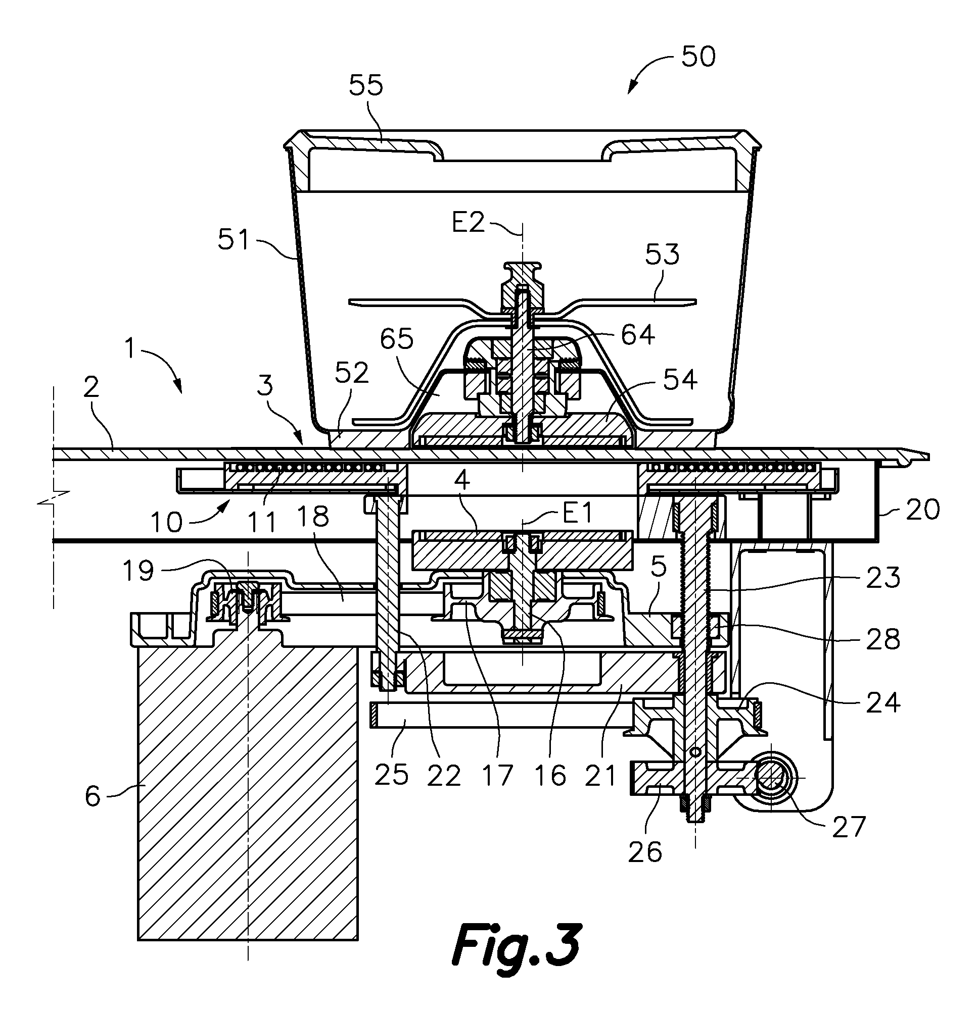
[0037]The treatment area 3 is configured for supporting the mentioned cooking vessel 50 which, as best shown in FIGS. 3, 4 and 5, comprises a vessel body 51 which has a bottom 52 configured for being heated by electromagnetic induction and an upper opening. Rotary blades or paddles 53 connected by means of a blade shaft...


PUM


Abstract

The hob (1) comprises a support plate (2) which has a treatment area (3) and the cooking vessel (50) has rotary blades (53) connected to an upper magnetic coupling member (54). Below the plate (2) of the hob (1) there is a lower magnetic coupling member (4) rotatably driven by an actuator (6) to magnetically transmit torque to the upper magnetic coupling member (54) of the vessel (50). The hob (1) includes a lower magnetic element (8) below the plate (2) and the vessel has an upper magnetic element (58), which are at the same predetermined distance from the rotating shafts (E1, E2) of the respective magnetic coupling members. When the vessel (50) is in a predetermined angular position, the magnetic attraction between the lower and upper magnetic elements (8, 58) applies opposition to the rotation of the vessel (50).

Description

FIELD OF THE ART[0001]The present invention relates to a cooking hob provided with a continuous support plate, made for example of glass, glass ceramic or the like, and rotary driving means located below the support plate for driving rotary blades or paddles installed in a cooking vessel located on a treatment area of the support plate. The present invention also relates to a cooking vessel usable with said cooking hob.BACKGROUND OF THE INVENTION[0002]U.S. Pat. No. 5,549,382 describes a cooking hob provided with a support plate having with several cooking areas, in each of which a cooking vessel can be supported. The hob includes heating means associated with each cooking area and driving means aligned with one of the cooking areas. The driving means comprise a motor which rotates a lower magnetic coupling member located below the support plate in a position close enough to it to magnetically transmit torque to an upper magnetic coupling member attached to a stirrer located inside a...

Claims


Application Information

Patent Timeline
Patent Type & Authority Patents(United States)
IPC IPC(8): H05B6/12B01F13/08A47J43/08B01F13/04B01F15/00A47J27/00B01F15/06B01F13/00A47J43/07A47J43/046B01F35/60
CPCA47J43/0777A47J27/004A47J43/0465A47J43/085B01F13/0033B01F13/045B01F13/0872B01F15/00175B01F15/00779B01F15/067H05B6/12H05B6/129H05B6/1209B01F33/5014B01F35/605B01F33/4535B01F35/2115B01F35/45B01F35/94B01F31/44
Inventor ALET VIDAL, JOSEPTRENCH ROCA, LLUISMONTRAVETA MONTRAVETA, FIDEL
Owner ELECTRODOMESTICOS TAURUS
Why Eureka
Try Eureka