
Medical connector

a technology of medical devices and connectors, applied in the field of medical devices, can solve the problems of affecting the performance of rapid procedures therewith, and achieve the effect of smooth medical procedures using medical devices

Active Publication Date: 2016-01-19
TERUMO KK
View PDF18 Cites 10 Cited by
  • Summary
  • Abstract
  • Description
  • Claims
  • Application Information

AI Technical Summary

Benefits of technology

[0008]According to the configuration of one aspect of the present invention, since the direction of the side port can be changed independently without rotating the main body, when a liquid injection tool is to be connected to the side port, it is possible to adjust the side port to be oriented to open in a selected direction. Consequently, connection of the liquid injection tool can be readily carried out. Further, even if the direction of the side port is changed, a device such as a medical catheter (for example, a balloon catheter) inserted in the main body will not rotate, and therefore, the procedure can be carried out smoothly.
[0010]According to the configuration described above, the cross-sectional area of the flow path, which provides communication between the lumen in the connector main body and the branch lumen, can be large, and movement of fluid from the branch to the connector main body can be carried out smoothly.
[0012]According to the configuration described above, the lumen and the branch lumen are always in reliable communication with each other through the space and the communication path irrespective of the positional relationship between the rotatable tubular portion and the connector main body in the circumferential direction. Therefore, the direction of the side port is not restricted, and connection of the liquid injection tool to the side port can be carried out more simply, easily, and thus rapidly.
[0014]According to the configuration described above, different from the conventional medical connector, the connection portion does not have rotatable structure, and therefore, the total length of the connector main body can be reduced accordingly. Therefore, the effective length of a medical device (for example, a medical catheter) to be inserted into and used with the medical connector can be maximized.
[0017]With the medical connector of one aspect of the present invention, the direction of the side port can be adjusted to a selected direction without rotating the medical device connected to the connector main body. Therefore, the medical procedure using the medical device can be carried out smoothly.
[0018]In another form, a medical connector is provided including an elongate main body having a longitudinal axis and a lumen extending axially therethrough, proximal and distal end portions of the elongate main body with the distal end portion being configured to be connected to a first tubular medical device, an auxiliary connection device having a port for being connected to a second tubular medical device, and an adjustable connection between the auxiliary connection device and the elongate main body that allows positioning of the port of the auxiliary connection device relative to the elongate main body to be adjustably selected by a user for ease in connecting the second tubular medical device to the auxiliary connection device.

Problems solved by technology

If a device such as a medical catheter rotates, then the direction of the distal end portion thereof may change, so that there is a concern that the performance of a rapid procedure therewith will be negatively influenced.

Method used


Image

  • Medical connector
  • Medical connector
  • Medical connector

Examples


Embodiment Construction

[0045]In the following a preferred embodiment of a medical connector according to the present invention is described with reference to the accompanying drawing.

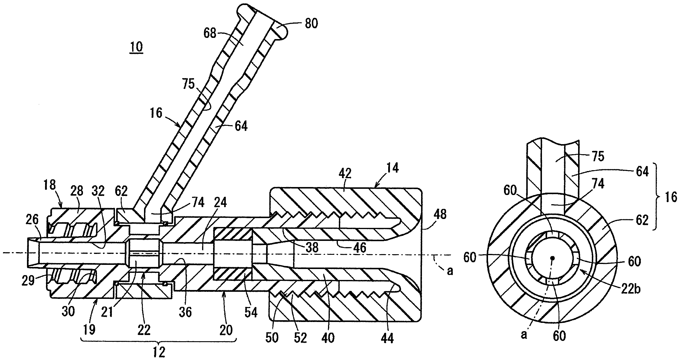
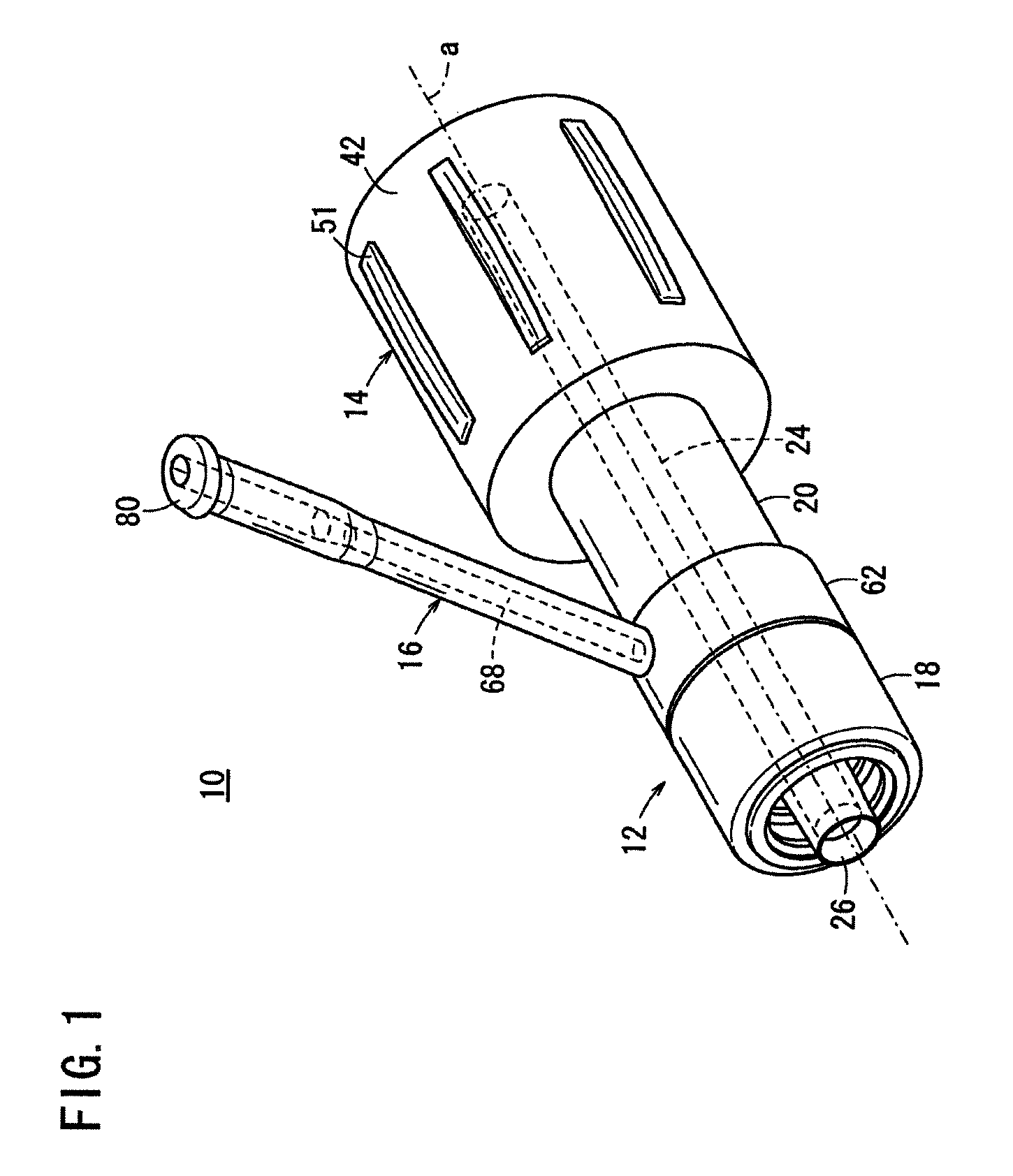
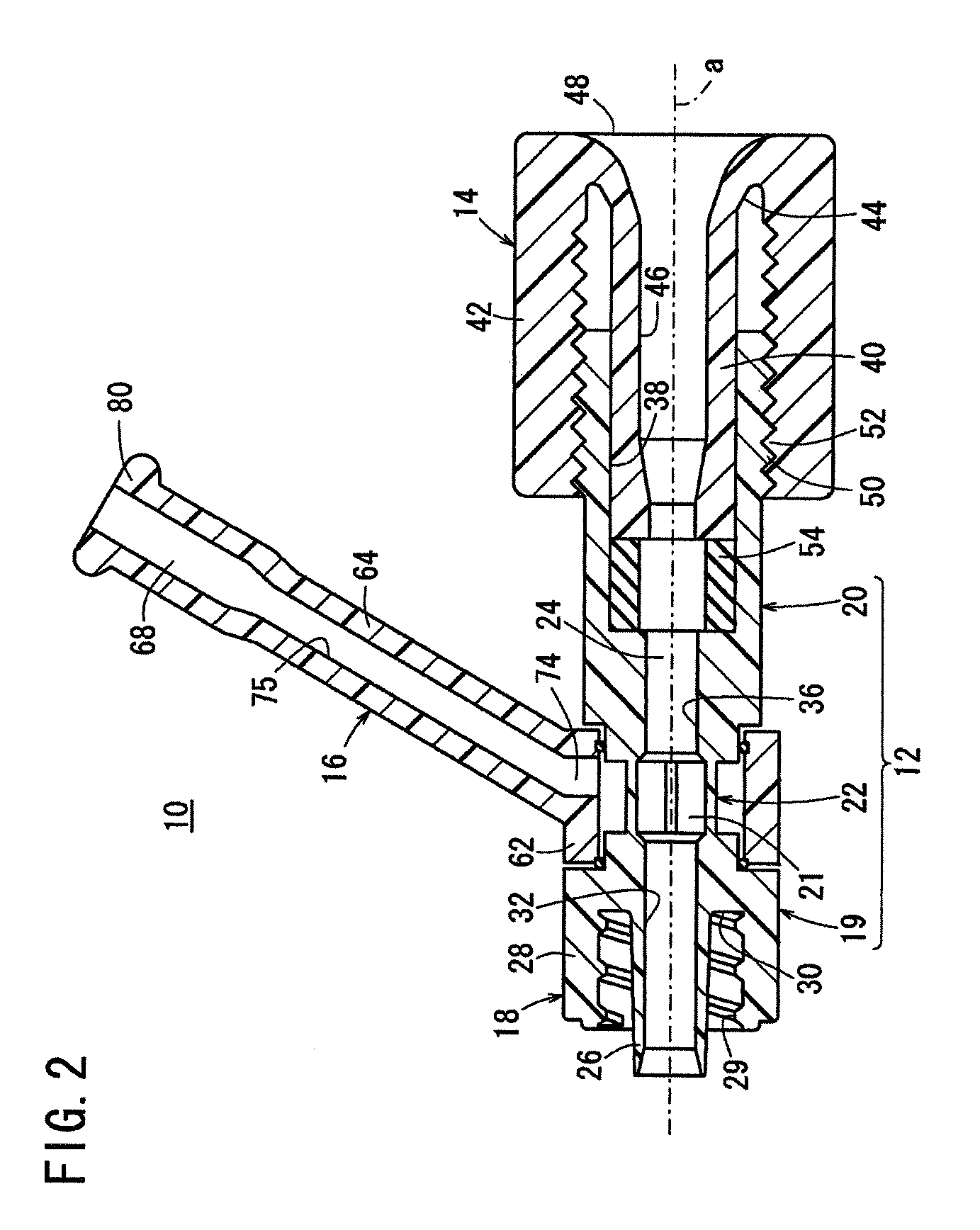
[0046]FIG. 1 is a perspective view of a medical connector 10 according to an embodiment of the present invention; FIG. 2 is a vertical sectional view taken along a direction of an axial line a of the medical connector 10; and FIG. 3 is a vertical sectional view showing the medical connector 10 in a state in which it is connected to a hub 84 of a catheter 82.

[0047]The present medical connector 10 is connected to a proximal end portion (hub) of and used together with a tubular medical apparatus. The tubular medical apparatus to which the medical connector 10 is connected is a catheter 82 such as, for example, a guiding catheter or a medical catheter (for example, a balloon catheter or a thrombus aspiration catheter) (refer to FIG. 3).

[0048]The medical connector 10 includes a connector main body 12, a cap member 14 provided at a...


PUM


Abstract

A medical connector and method of using the medical connector are provided. In one form, the medical connector includes an elongate main body having a longitudinal axis and a lumen extending axially therethrough, proximal and distal end portions of the elongate main body with the distal end portion being configured to be connected to a first tubular medical device, an auxiliary connection device having a port for being connected to a second tubular medical device, and an adjustable connection between the auxiliary connection device and the elongate main body that allows positioning of the port of the auxiliary connection device relative to the elongate main body to be adjustably selected by a user for ease in connecting the second tubular medical device to the auxiliary connection device.

Description

CROSS-REFERENCE TO RELATED APPLICATIONS[0001]This application is a continuation of International Application Number PCT / JP2011 / 079651, filed on Dec. 21, 2011, which claims priority from JP 2011-039159, filed on Feb. 25, 2011, which are hereby incorporated herein by reference in their entirety.FIELD OF THE INVENTION[0002]The present invention relates to a medical connector connected to a proximal end portion of and used together with a tubular medical device.BACKGROUND OF THE INVENTION[0003]In order to treat a blood vessel (vasculature) abnormally narrowed by arteriosclerosis or the like, percutaneous transluminal coronary angioplasty (PTCA) is applied wherein a catheter having a dilation body at a distal end portion thereof is inserted into a stenosed site and the dilation body is inflated to expand the stenosed site thereby to improve the peripheral blood flow. This technique is carried out generally in the following manner. In particular, before a catheter with a dilation body (ba...

Claims


Application Information

Patent Timeline
Patent Type & Authority Patents(United States)
IPC IPC(8): A61M25/16A61M39/10A61M25/00A61M25/01
CPCA61M39/10A61M39/1055A61M39/105A61M25/0097A61M25/0105
Inventor MOURI, TAKAYUKI
Owner TERUMO KK
Learn More