Optical measurement probe, and optical measurement device provided with the same

a technology of optical measurement and probe, which is applied in the direction of optical radiation measurement, instruments, spectrometry/spectrophotometry/monochromator, etc., can solve the problems of reducing analysis accuracy, greasy dirt easily adhering to sapphire, and high lipophilic property, so as to prevent dirt adhesion to the incidence surface and achieve stable measurement results

Inactive Publication Date: 2016-01-19
SHIMADZU CORP +1
View PDF8 Cites 0 Cited by
  • Summary
  • Abstract
  • Description
  • Claims
  • Application Information

AI Technical Summary

Benefits of technology

[0008]When measurement is performed with dirt adhered to the incidence surface of the optical window, the adhered matter may considerably absorb light of a specific wavelength. Also, the amount of received light may be reduced due to the adhered matter preventing transmission of light regardless of the wavelength of light. In this case, even if light emission at the time of combustion is constant, measurement results may vary, and the accuracy of analysis may be reduced.
[0024]According to the present invention, by covering the incidence surface of the optical window by the deposited film, adhesion of dirt to the incidence surface can be prevented, and a measurement result can be prevented from being affected by the adhesion of dirt to the incidence surface, and thus, a more stable measurement result can be obtained.

Problems solved by technology

However, sapphire has a high lipophilic property, and there is a problem that greasy dirt easily adheres to the sapphire.
In this case, even if light emission at the time of combustion is constant, measurement results may vary, and the accuracy of analysis may be reduced.

Method used


Image

  • Optical measurement probe, and optical measurement device provided with the same
  • Optical measurement probe, and optical measurement device provided with the same
  • Optical measurement probe, and optical measurement device provided with the same

Examples


Embodiment Construction

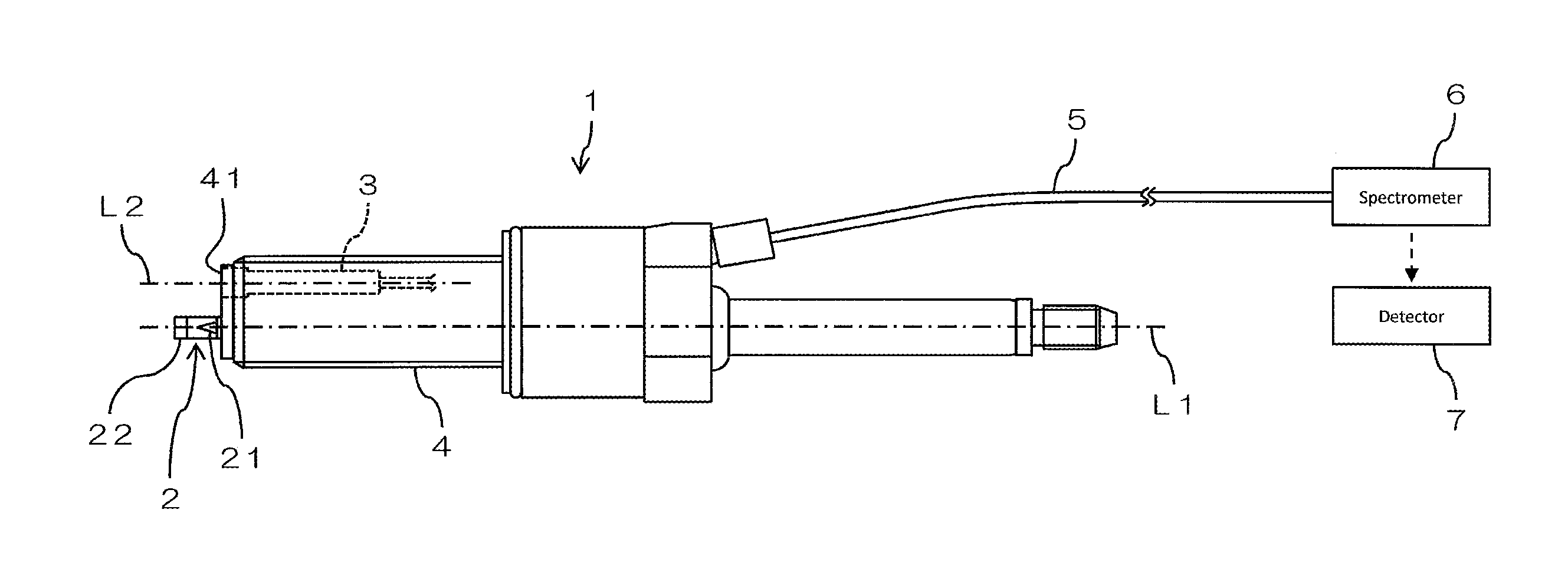
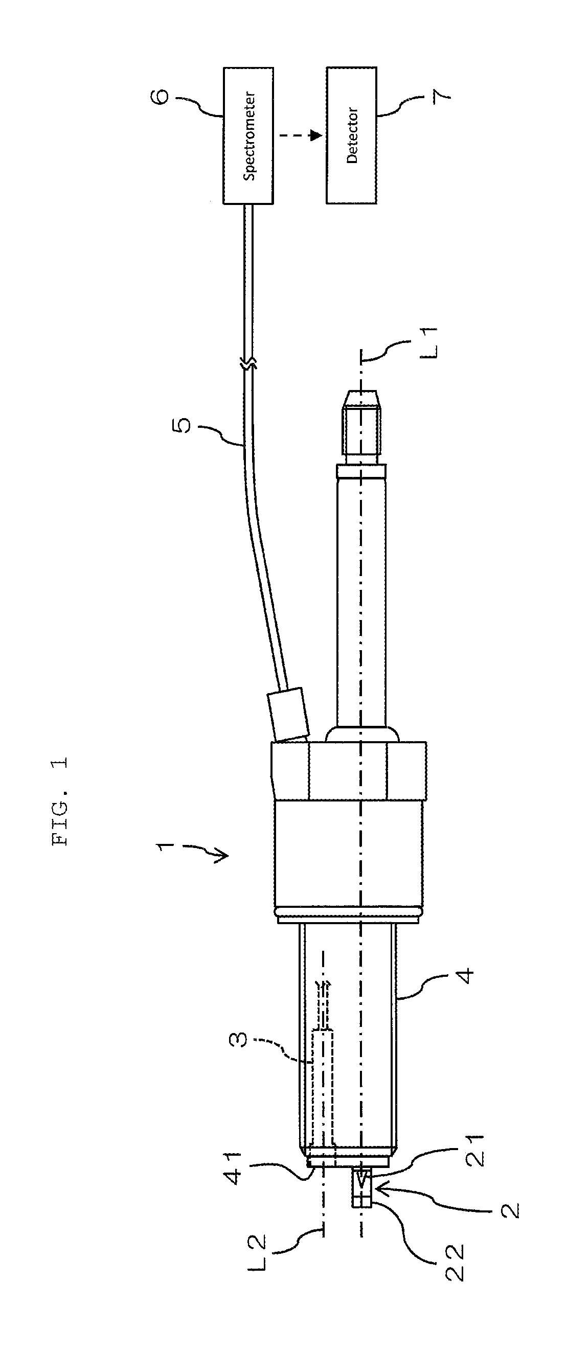
[0031]FIG. 1 is a view showing a structure example of an optical measurement device provided with an optical measurement probe 1 according to an embodiment of the present invention. FIG. 1 shows a schematic side view of a concrete structure of the optical measurement probe 1, and also a block diagram of other structures.

[0032]The optical measurement probe 1 according to the present embodiment is for guiding light generated in a high temperature environment to an appliance, and is installed in a combustion chamber of an internal combustion engine of a car, a motorcycle or the like, and is used at a time of evaluating the combustion state in the combustion chamber, for example. The high temperature environment is an environment of 300° C. or higher, for example, and the optical measurement probe 1 according to the present embodiment is heat-resistant in an environment of 300° C. or higher, and more preferably, 800° C. or higher. Additionally, “heat resistance” here means a property ac...


PUM

PropertyMeasurementUnit
temperatureaaaaaaaaaa
optical measurementaaaaaaaaaa
temperatureaaaaaaaaaa

Abstract

There are provided an optical measurement probe capable of obtaining a more stable measurement result, and an optical measurement device provided with the same. An incidence surface of an optical window to be used in a high temperature environment is covered by a deposited film. The optical window is formed of sapphire, and the deposited film is formed from SiO2. Adhesion of dirt to the incidence surface, and an influence, on a measurement result, of the adhesion of dirt on the incidence surface can thereby be prevented, and a more stable measurement result can be obtained.

Description

BACKGROUND OF THE INVENTION[0001]1. Field of the Invention[0002]The present invention relates to an optical measurement probe for guiding light generated in a high temperature environment to an appliance, and an optical measurement device provided with the same.[0003]2. Description of the Related Art[0004]For example, at the time of evaluating the combustion state in a combustion chamber of an internal combustion engine of a car, measurement is performed using an optical measurement probe for guiding light generated at the time of combustion to an appliance (for example, see JP-A-2012-118080, and JP-A-2011-241753). Such an optical measurement probe to be used in a high temperature environment has to be designed by giving enough consideration to heat resistance.[0005]The optical measurement probe is provided with an optical window, and a light guide, for example. Light generated in a high temperature environment enters from an incidence surface of a transparent optical window, and li...

Claims


Application Information

Patent Timeline
Patent Type & Authority Patents(United States)
IPC IPC(8): G01J3/28G01M15/04G01N21/958G01N21/94G01N21/67G01D5/353G01N21/15F02P13/00G01J5/04G01J5/00G01J5/08G02B1/02G02B6/26F02D35/02H01T13/40G01J3/02
CPCG01M15/042G01N21/94G01N21/958G02B1/02F02P13/00G01N21/15G01N21/67G01J5/0821G01J5/0014G01J5/042G01J5/043G01D5/353G01J3/0218G01N2201/08G02B6/262H01T13/40F02D35/022G02B7/007G02B1/14G01J5/05
Inventor NAGAI, TETSUYAIWAI, NOBUYUKIFURUKAWA, YASUYUKIHIRAOKA, RYOJIAZUMAGAKITO, ISAOOKADA, SATORU
Owner SHIMADZU CORP
Why Eureka
Try Eureka