Contrast adjusted anaglyph for reducing ghosting artifacts

a contrast adjustment and anaglyph technology, applied in image enhancement, image analysis, instruments, etc., can solve the problems of distracting, degrading imaging quality, etc., to reduce or eliminate ghosting artifacts, distract viewers, and degrade imaging quality

Active Publication Date: 2016-01-19
STMICROELECTRONICS INT NV
View PDF7 Cites 1 Cited by
  • Summary
  • Abstract
  • Description
  • Claims
  • Application Information

AI Technical Summary

Benefits of technology

[0005]Methods and apparatus for producing contrast-adjusted anaglyphs are described. Adjusting contrast in an anaglyph imaging technique can introduce ghosting artifacts in anaglyph images. The ghosting artifacts can degrade the imaging quality and be distracting to a viewer. The methods and apparatus described herein employ signal processing and compensation techniques to reduce or eliminate ghosting artifacts that would otherwise be introduced by contrast adjustments.
[0007]According to some embodiments, the system for adjusting contrast of an anaglyph image may further comprise at least one downstream summing device configured to subtract the first difference from the first input image signal to produce a first compensated image signal, and to subtract the second difference from the second input image signal to produce a second compensated image signal. The system may further include a second anaglyph transformer configured to generate a second anaglyph signal from the first compensated image signal and the second compensated image signal. The generated second anaglyph signal may comprise a 2D composite contrast-adjusted anaglyph signal for generating a 2D composite anaglyph image that is to be displayed on a video display. When viewed using 3D spectacles, the 2D composite image may exhibit reduced or substantially eliminated ghosting artifacts.

Problems solved by technology

The ghosting artifacts can degrade the imaging quality and be distracting to a viewer.

Method used


Image

  • Contrast adjusted anaglyph for reducing ghosting artifacts
  • Contrast adjusted anaglyph for reducing ghosting artifacts
  • Contrast adjusted anaglyph for reducing ghosting artifacts

Examples


Embodiment Construction

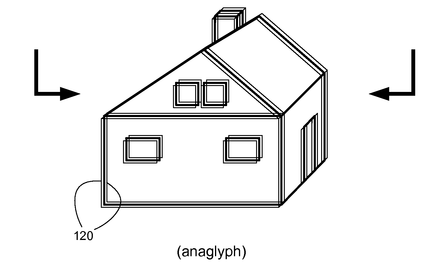
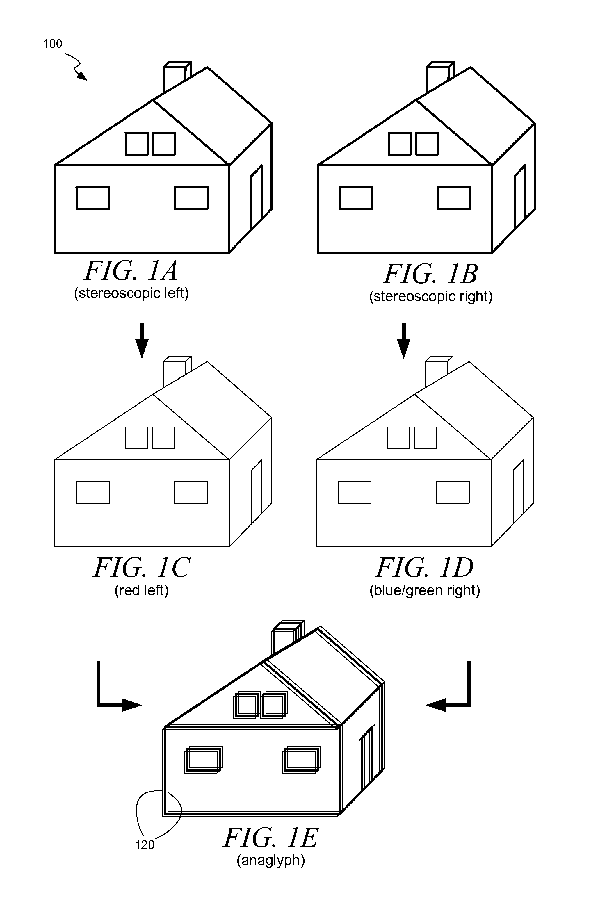
[0019]By way of introduction, FIGS. 1A-1E depict one process by which an anaglyph image may be formed. An image of a scene may first be captured as a stereoscopic pair 100 of images (e.g., left and right). In one embodiment, the pair of images may be color images that are used to produce a color anaglyph, and may correspond to images that would be perceived separately by an individual's left and right eyes. The pair of images 100 (FIG. 1A, FIG. 1B) may appear to be nearly identical, except they may be recorded from different angles.

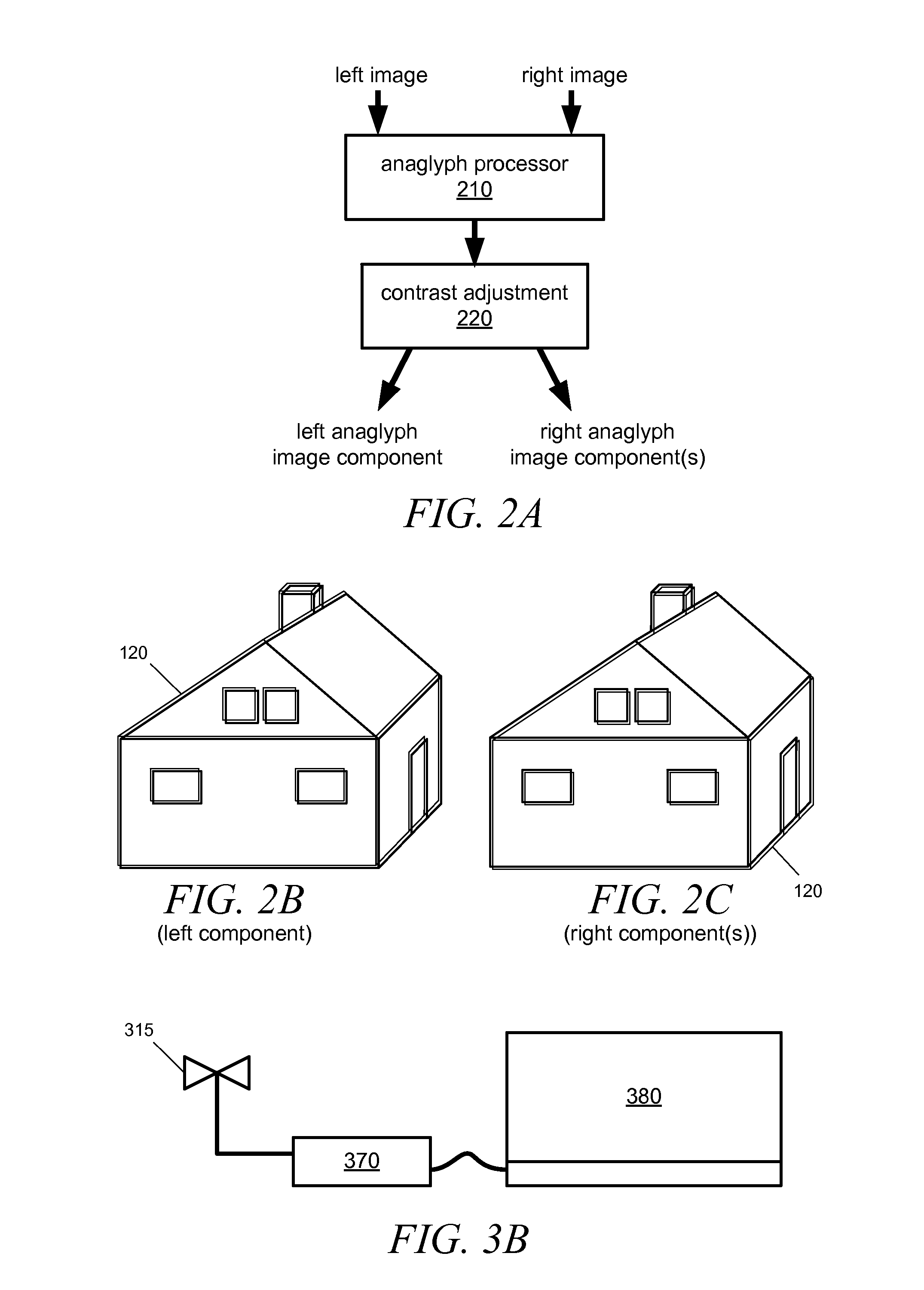
[0020]To produce anaglyph images, the images may be processed. Each image may be a color image, and may be represented using a tri-color basis, e.g., red, blue, and green. Other color bases including black, white, and / or grayscale bases, may be used in other embodiments of anaglyph imaging, and in some cases colors may be altered to produce black and white or grayscale anaglyphs. To prepare an anaglyph image, components of each stereographic image may be ...


PUM


Abstract

A system adjusts contrast of an anaglyph image and includes a contrast adjuster processor that generates a contrast-adjusted first luma signal and second luma signal and a contrast-adjusted third luma signal from a first input image signal and second input image signal. An upstream summing node determines a first difference between the first luma signal and third luma signal and a downstream summing node subtracts the first difference from the first signal component of the first input signal. A fine adjuster circuit receives a signal for the first difference and applies a fine adjustment as a gain adjustment, an offset adjustment, and a horizontal and vertical shift.

Description

BACKGROUND[0001]1. Technical Field[0002]The technology relates to stereographic image processing, and more particularly to reducing ghosting artifacts associated with contrast adjustments to anaglyph images.[0003]2. Discussion of the Related Art[0004]Anaglyph imaging is a technique for producing three-dimensional (3D) images of an object. The images may be still images or video images. Anaglyph imaging involves producing stereoscopic image pairs, typically left and right stereoscopic images. The stereoscopic images may be processed to form a single two-dimensional (2D) anaglyph image that can be printed on an object, e.g., in a magazine, or that can be electronically displayed, e.g., on a video display or television. The single anaglyph image may be viewed through spectacles having different color filters for the left and right eyes, so that the viewer perceives a three-dimensional (3D) rendering of the scene when viewing the 2D anaglyph image. Anaglyph imaging techniques can enable...

Claims


Application Information

Patent Timeline
Patent Type & Authority Patents(United States)
IPC IPC(8): G02B27/22G06T5/00G06T5/50H04N13/04H04N13/00H04N13/122
CPCG06T5/008H04N13/0018H04N13/0025H04N13/0431G06T5/50G06T2207/10021G06T2207/10024H04N13/133H04N13/334H04N13/122
Inventor HUI, LUCAS
Owner STMICROELECTRONICS INT NV
Why Eureka
Try Eureka