
Pressure/vacuum actuated catheter forceps

a pressure/vacuum actuated catheter and forcep technology, applied in the field of medical diagnosis and treatment, can solve the problems of forceps and devices, a large number of known biopsy tools, and the inability to take sufficient sample quantities, etc., to facilitate the transbronchial biopsy of a specific lymph node, the effect of facilitating the transbronchial sampling of a lymph node tissu

Active Publication Date: 2016-01-26
SANOVAS
View PDF24 Cites 170 Cited by
  • Summary
  • Abstract
  • Description
  • Claims
  • Application Information

AI Technical Summary

Benefits of technology

The present invention provides a catheter forceps for extracting tissue samples that can be precisely positioned and actuated to sample indirect tissues, such as those positioned beyond the walls of an airway, lumen or vessel. The catheter forceps is capable of being precisely positioned and actuated to sample indirect tissues, such as a transbronchial sampling of a lymph node tissue. Additionally, the catheter forceps is repetitively actuated, meaning its insertion, actuation, depth and repetition cycles are known and controlled. The catheter forceps can also be navigated using direct and / or indirect visualization methods to facilitate sampling of indirect tissues.

Problems solved by technology

However, the known biopsy tools suffer from a number of disadvantages and shortcomings.
For example, the prior art biopsy forceps and devices are typically limited to taking a single tissue sample, after which the device may be withdrawn from the patient's body and the tissue collected before the device can be used again to take a second tissue sample.
Accordingly, it is a major disadvantage of the existing art to take sufficient sample quantities in an expeditious manner.
An additional disadvantage of prior art devices is that it is often very difficult to accurately position the forceps next to the tissue to be sampled.
Yet another disadvantage of prior art devices is that the samples are not immediately captured and securely held in a container at the sample site.

Method used


Image

  • Pressure/vacuum actuated catheter forceps
  • Pressure/vacuum actuated catheter forceps
  • Pressure/vacuum actuated catheter forceps

Examples


Embodiment Construction

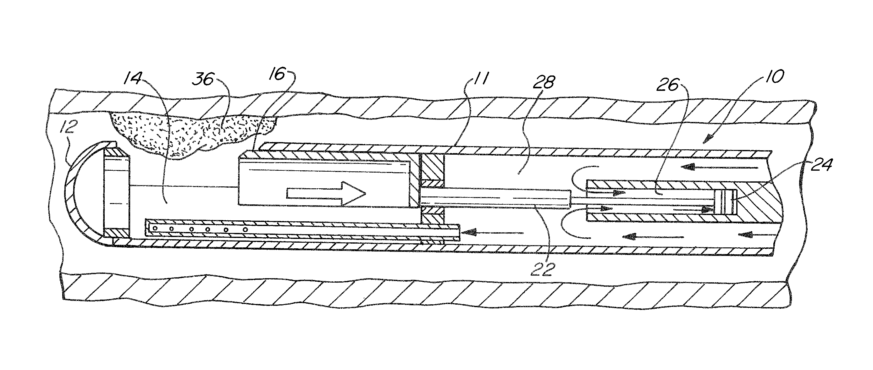
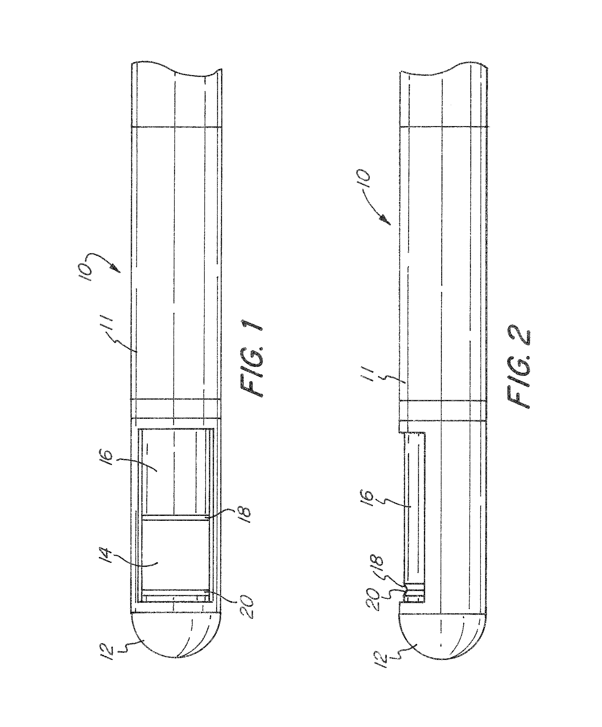
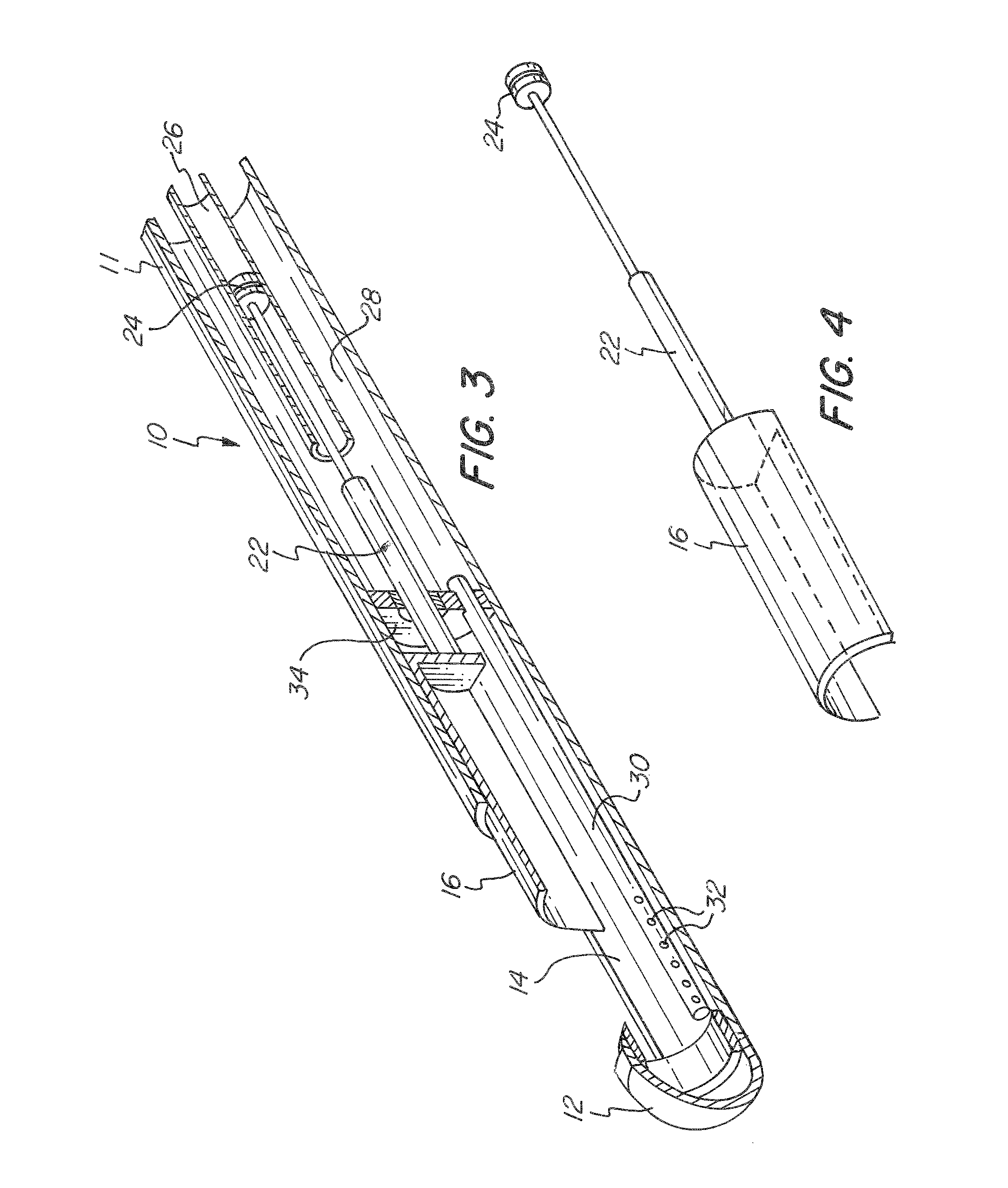
[0051]The basic components of one embodiment of a pressure / vacuum actuated catheter forceps in accordance with the invention are illustrated in FIG. 1. As used in the description, the terms “top,”“bottom,”“above,”“below,”“over,”“under,”“above,”“beneath,”“on top,”“underneath,”“up,”“down,”“upper,”“lower,”“front,”“rear,”“back,”“forward” and “backward” refer to the objects referenced when in the orientation illustrated in the drawings, which orientation is not necessary for achieving the objects of the invention.

[0052]It should be understood that the foregoing is illustrative and not limiting, and that obvious modifications may be made by those skilled in the art without departing from the spirit of the invention. Accordingly, reference should be made primarily to the accompanying claims, rather than the foregoing specification, to determine the scope of the invention.

[0053]The pressure / vacuum actuated catheter forceps of the present invention may be used with various catheter devices, ...


PUM


Abstract

A method for extracting a tissue sample is provided, including the steps of inserting a catheter into a bodily cavity, the catheter having a sampling chamber, a movable cover, and an actuation mechanism for actuating the cover, positioning the sampling chamber next to tissue to be sampled, providing a fluid to the actuation mechanism to open the cover, supplying a vacuum to draw tissue sample into the sampling chamber and to close the cover, and withdrawing the catheter from the bodily cavity. Catheter forceps for obtaining a tissue sample are also provided, including a catheter, a sampling chamber positioned at a distal end of the catheter and having a movable cover, and an actuation mechanism for moving the movable cover to an opened position by providing a fluid to the actuation mechanism and to a closed position by providing a vacuum to the actuation mechanism.

Description

CROSS-REFERENCE TO RELATED APPLICATIONS[0001]The present application claims the benefit under 35 U.S.C. §119(e) of the U.S. Provisional Patent Application Ser. No. 61 / 328,969 filed on Apr. 28, 2010, the content of which is incorporated herein by reference.FIELD OF THE INVENTION[0002]The invention relates to the field of medical diagnosis and treatment. More specifically, the invention relates to catheter forceps that are actuated by pressurized fluid and / or vacuum, and are adapted for tissue sampling and withdrawal for examination and analysis.BACKGROUND OF THE INVENTION[0003]Biopsy is a commonly performed medical procedure in which tissue samples are obtained for diagnostic purposes. Such a procedure typically includes cutting a tissue sample and then retrieving the sample from a patient's body.[0004]Numerous types of biopsy forceps and devices have been developed for in vivo medical diagnosis and treatment of different conditions. Such devices are designed for sampling tissue with...

Claims


Application Information

Patent Timeline
Patent Type & Authority Patents(United States)
IPC IPC(8): A61B10/00A61B10/04A61B10/02
CPCA61B10/04A61B10/0275
Inventor GUNDAY, ERHAN H.GERRANS, LAWRENCE J.
Owner SANOVAS
Learn More