Load release system

a technology of load release and load, which is applied in the direction of load-engaging elements, anchoring installations, emergency apparatuses, etc., can solve the problems of rotary aircraft sensitive to weight imbalance, unsuitable for purposes, and directional instability of load as well as aircraft, etc., to achieve easy manufacturing, low cost, and quick attachment

Active Publication Date: 2016-01-26
AIR RESCUE SYST
View PDF16 Cites 17 Cited by
  • Summary
  • Abstract
  • Description
  • Claims
  • Application Information

AI Technical Summary

Benefits of technology

[0012]It is an object of the invention to provide an automatic and quick load release system and method that can be adapted to function as both a manual quick release and an automatic system break away to safely release an aerial load from an anchor.
[0013]It is another object of the invention to provide an easy to manufacture and low cost automatic load release system that has quick attachment features so as to facilitate quick attachment of the load release system to the aerial load and the anchor.

Problems solved by technology

Rotary aircrafts are sensitive to weight imbalance, especially while holding an external load.
A common problem in addition to other numerous problems encountered when conventional method and system for difficulty in attaching and releasing an anchor from the external loads attached to the aircraft.
Excessive load or movement of the load due to the movement of the aircraft or due to other environmental factors causing directional instability of the load as well as the aircraft.
Furthermore, even though these innovations may be suitable for the specific purposes to which they address, accordingly, they would not be suitable for the purposes of the present invention as heretofore described.

Method used


Image

  • Load release system
  • Load release system
  • Load release system

Examples


Embodiment Construction

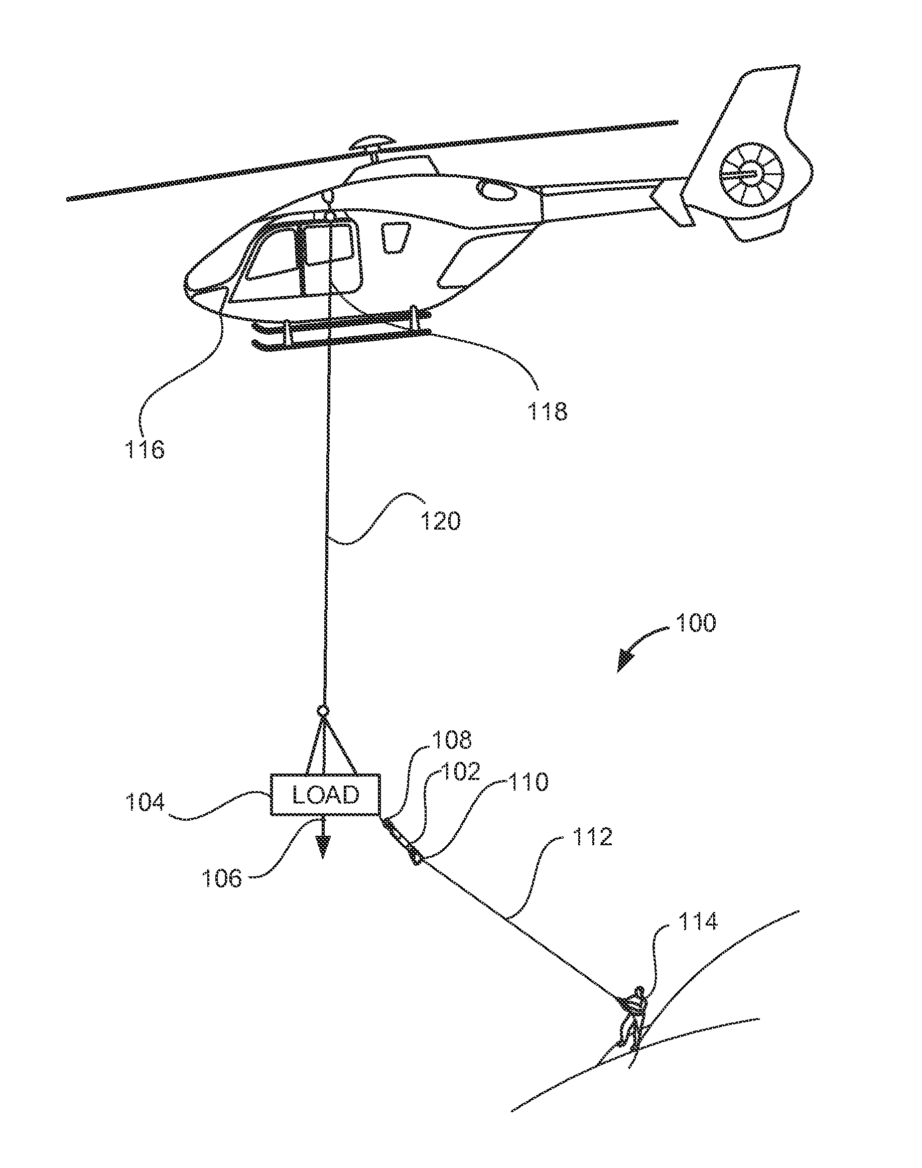
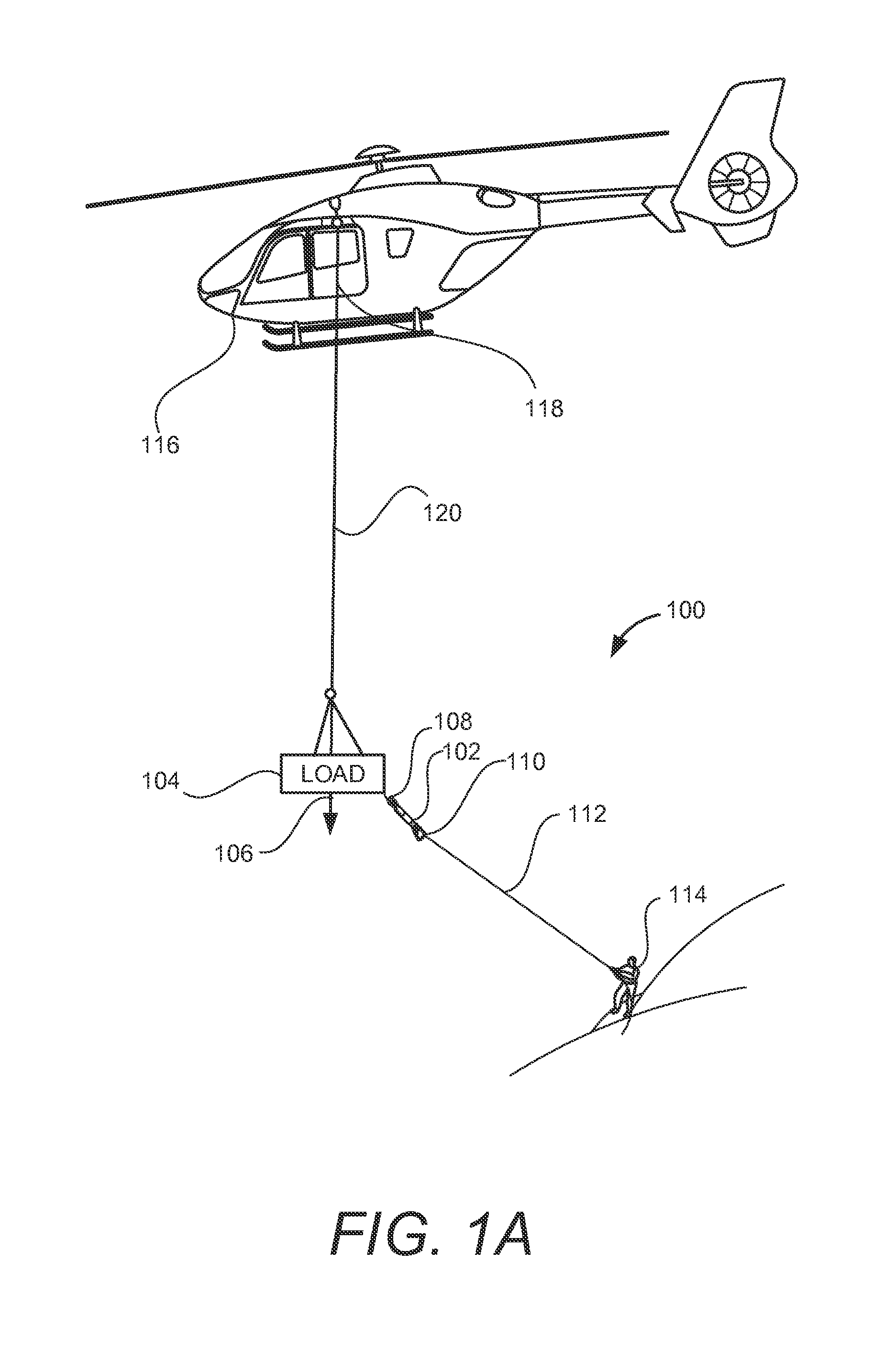
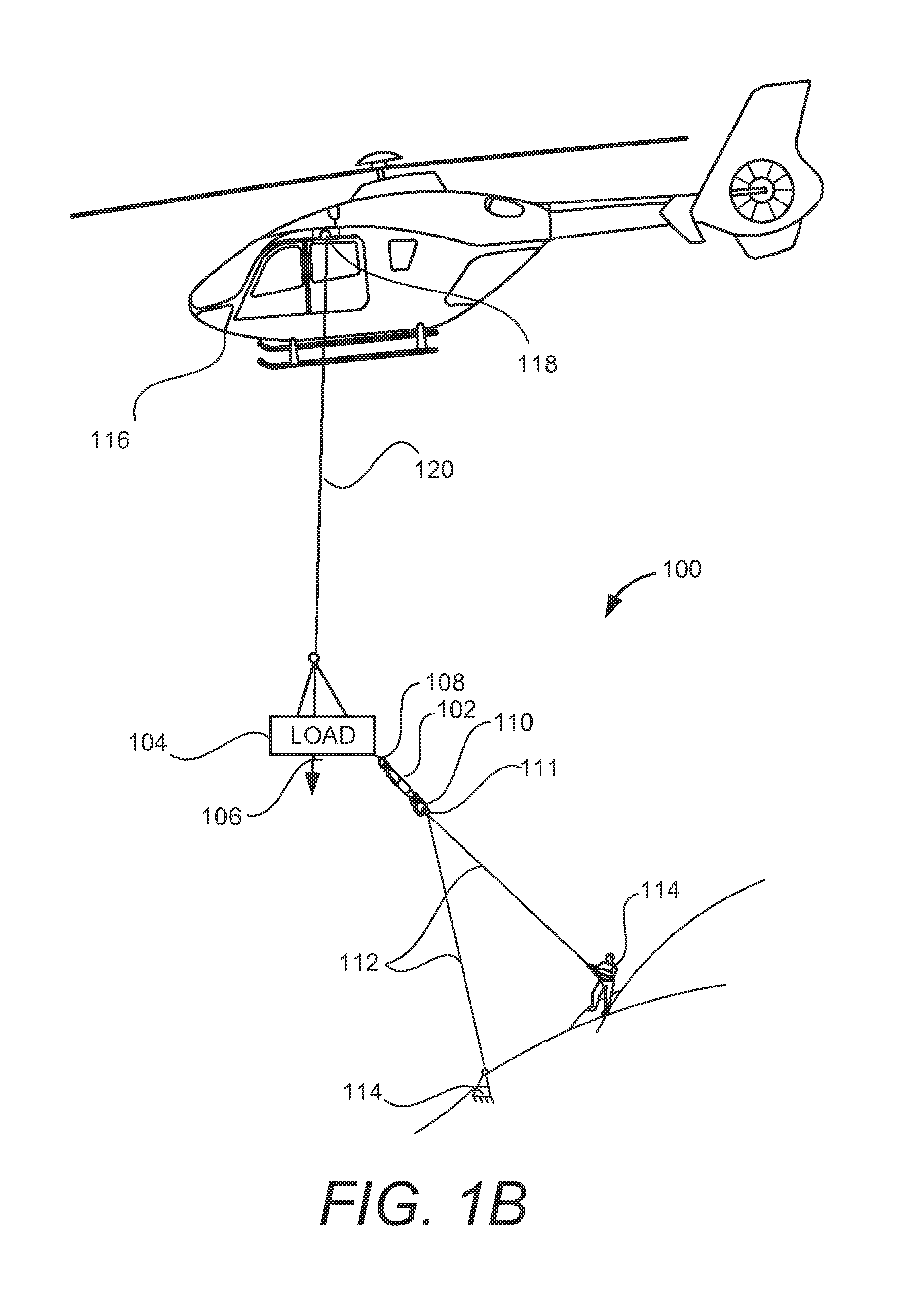
[0021]The following detailed description is merely exemplary in nature and is not intended to limit the described embodiments or the application and uses of the described embodiments. As used herein, the word “exemplary” or “illustrative” means “serving as an example, instance, or illustration.” Any implementation described herein as “exemplary” or “illustrative” is not necessarily to be construed as preferred or advantageous over other implementations. All of the implementations described below are exemplary implementations provided to enable persons skilled in the art to make or use the embodiments of the disclosure and are not intended to limit the scope of the disclosure, which is defined by the claims. For purposes of description herein, the terms “upper,”“lower,”“left,”“rear,”“right,”“front,”“vertical,”“horizontal,” and derivatives thereof shall relate to the invention as oriented in FIG. 1A. Furthermore, there is no intention to be bound by any expressed or implied theory pre...


PUM


Abstract

A load release system provides load control safety for a rotary aircraft by automatically and manually releasing a load from an attached anchor when a predetermined load design point is reached. The system includes a cord that is disposed to extend between the load and the anchor, often through an anchor line. The cord is configured to release the load manually or automatically at a predetermined load design point, such as an excessive force, weight, tension, or movement. A load end includes a carabiner that manually attaches to and releases from the load. An anchor end includes a manual quick release ring with a pivoting end that is locked and released with a pin. The manual quick release ring is manually attached to and released from the anchor. An automatic release section automatically separates when the predetermined load design point is reached.

Description

CROSS-REFERENCES TO RELATED APPLICATIONS[0001]The present application claims priority from U.S. Provisional Application Ser. No. 61 / 942,682 filed on 21 Feb. 2014 which is hereby incorporated herein by reference in its entirety.FIELD OF THE INVENTION[0002]The present invention relates generally to a load release system for releasing a load from an anchor and in particular, the load release system enables both manual quick release and automatic separation mechanisms of an aircraft and an attached load to the aircraft from an anchor.BACKGROUND OF THE INVENTION[0003]Rotary aircrafts are sensitive to weight imbalance, especially while holding an external load. A common problem in addition to other numerous problems encountered when conventional method and system for difficulty in attaching and releasing an anchor from the external loads attached to the aircraft. Excessive load or movement of the load due to the movement of the aircraft or due to other environmental factors causing direct...

Claims


Application Information

Patent Timeline
Patent Type & Authority Patents(United States)
IPC IPC(8): B64F1/16B64D17/38
CPCB64F1/16B64D17/383B64D1/22B66C1/14B66C1/18B66C1/38
Inventor COCKELL, II, ROBERT, C.
Owner AIR RESCUE SYST
Why Eureka
Try Eureka