Image forming apparatus

a technology of image bearing and forming apparatus, which is applied in the direction of electrographic process apparatus, instruments, optics, etc., can solve the problem that the transfer belt cannot be reliably retracted from the image bearing member

Active Publication Date: 2016-01-26
CANON KK
View PDF21 Cites 3 Cited by
  • Summary
  • Abstract
  • Description
  • Claims
  • Application Information

AI Technical Summary

Benefits of technology

[0007]The present invention has been accomplished in view of the above-described circumferences. A principal object of the present invention is to provide an image forming apparatus including a structure capable of preventing re-contact of a belt member with an image bearing member caused by overrun of a gear when an operating portion is operated so as to space the belt member from the image bearing member.
[0008]According to an aspect of the present invention, there is provide an image forming apparatus comprising: an image bearing member; a belt member provided movably toward and away from the image bearing member; an operating lever movable between a first position where the belt member and the image bearing member are in a contact state and a third position where the belt member and the image bearing member are in a spaced state, wherein between the first position and the third position, a second position where the belt member and the image bearing member are switched between the contact state and the spaced state is located; a cam for transiting the belt member and the image bearing member between the contact state and the spaced state by transmitting thereto a driving force for moving the operating lever to rotate the cam; a transmitting mechanism for transmitting the driving force for moving the operating lever, wherein when the operating lever is moved between the first position and the third position, the transmitting mechanism transmits the driving force to the cam during passing of the operating lever between the first position and the second position and eliminates transmission of the driving force to the cam during passing of the operating lever between the second position and the third position; and a rotation stopping mechanism for stopping, when the operating lever is moved from the first position to the third position, rotation of the cam to maintain the spaced state so that the belt member and the image bearing member are prevented from being transited from the spaced state to the contact state by continuation of the rotation of the cam by inertia.
[0009]According to the present invention, the rotation stopping mechanism for stopping the rotation of the gear is provided and therefore when the operating portion is operated so as to space the belt member from the image bearing member, it is possible to prevent the re-contact of the belt member with the image bearing member caused by the overrun of the gear.

Problems solved by technology

However, the transfer belt cannot be reliably retracted from the image bearing member in some cases including the case where supply of energy to the motor, the solenoid or the like as the driving source for the transfer belt moving mechanism is blocked and the case where the driving source caused an abnormal operation.

Method used


Image

  • Image forming apparatus
  • Image forming apparatus
  • Image forming apparatus

Examples


first embodiment

[0027]First Embodiment of the present invention will be described with reference to FIG. 1 to FIG. 7. First, a general structure of an image forming apparatus including a belt unit in this embodiment will be described with reference to FIGS. 1 and 2.

[Image Forming Apparatus]

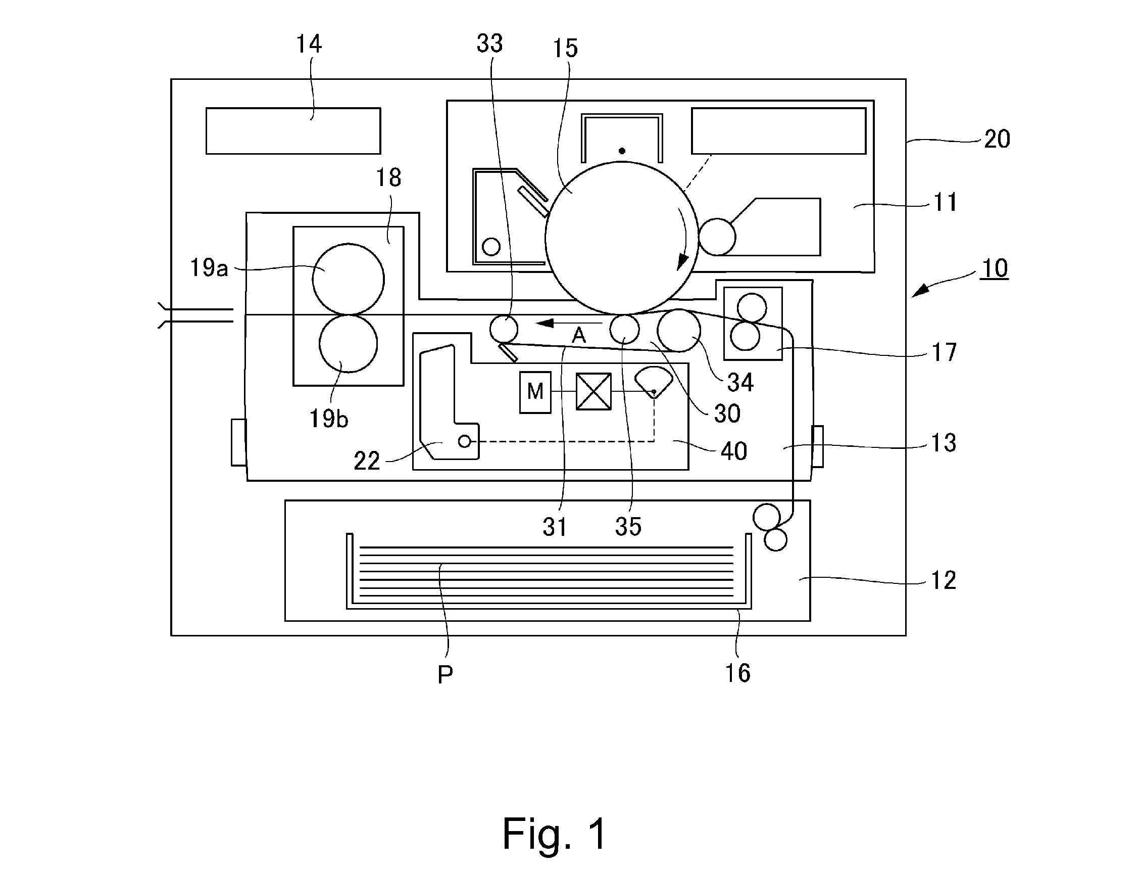
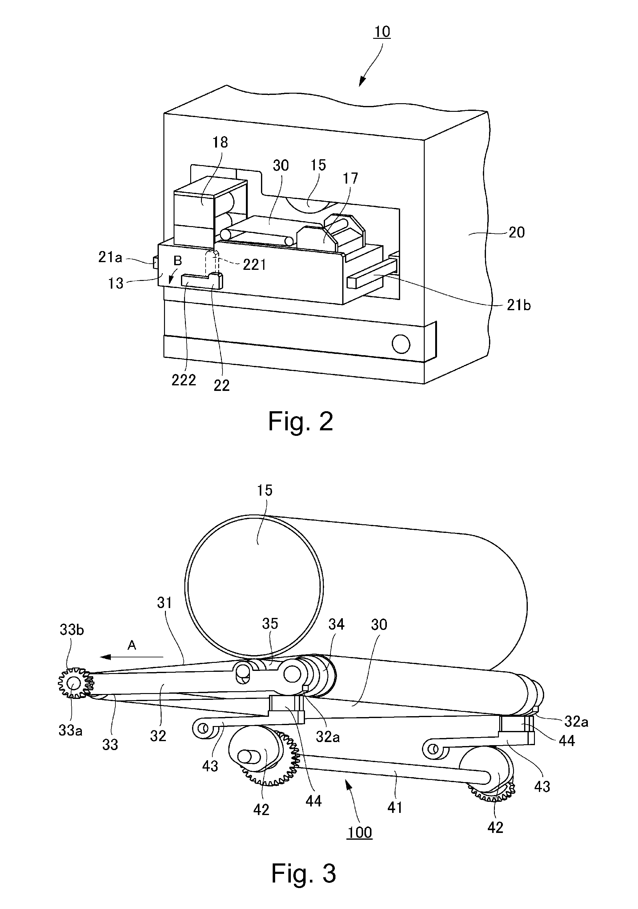
[0028]As shown in FIG. 1, a digital printer 10 as the image forming apparatus of an electrophotographic type includes an image forming portion 11, a sheet feeding portion 12, a conveying unit as a belt unit, and a controller (control portion) 14.

[0029]At the image forming portion 11, toner image formation which starts from lower exposure depending on an image signal and which uses an electrophotographic process is effected on a photosensitive drum (photosensitive member) 15 as an image bearing member provided inside an apparatus main assembly. The sheet feeding portion feeds a recording material P, stacked in a sheet cassette 16, toward the conveying unit 13. The conveying unit 13 including a registration device ...

second embodiment

[0067]Second Embodiment of the present invention will be described with reference to FIG. 8 to FIG. 10. In the case of this embodiment, the rotation stopping mechanism for the transfer belt moving mechanism is different from that in First Embodiment described above. Other constitutions and actions are the same as those in First Embodiment and therefore in the following, redundant description and illustration are omitted or simplified and repeated reference numeral or symbols and repeated names are used as they are, and a different portion will be principally described.

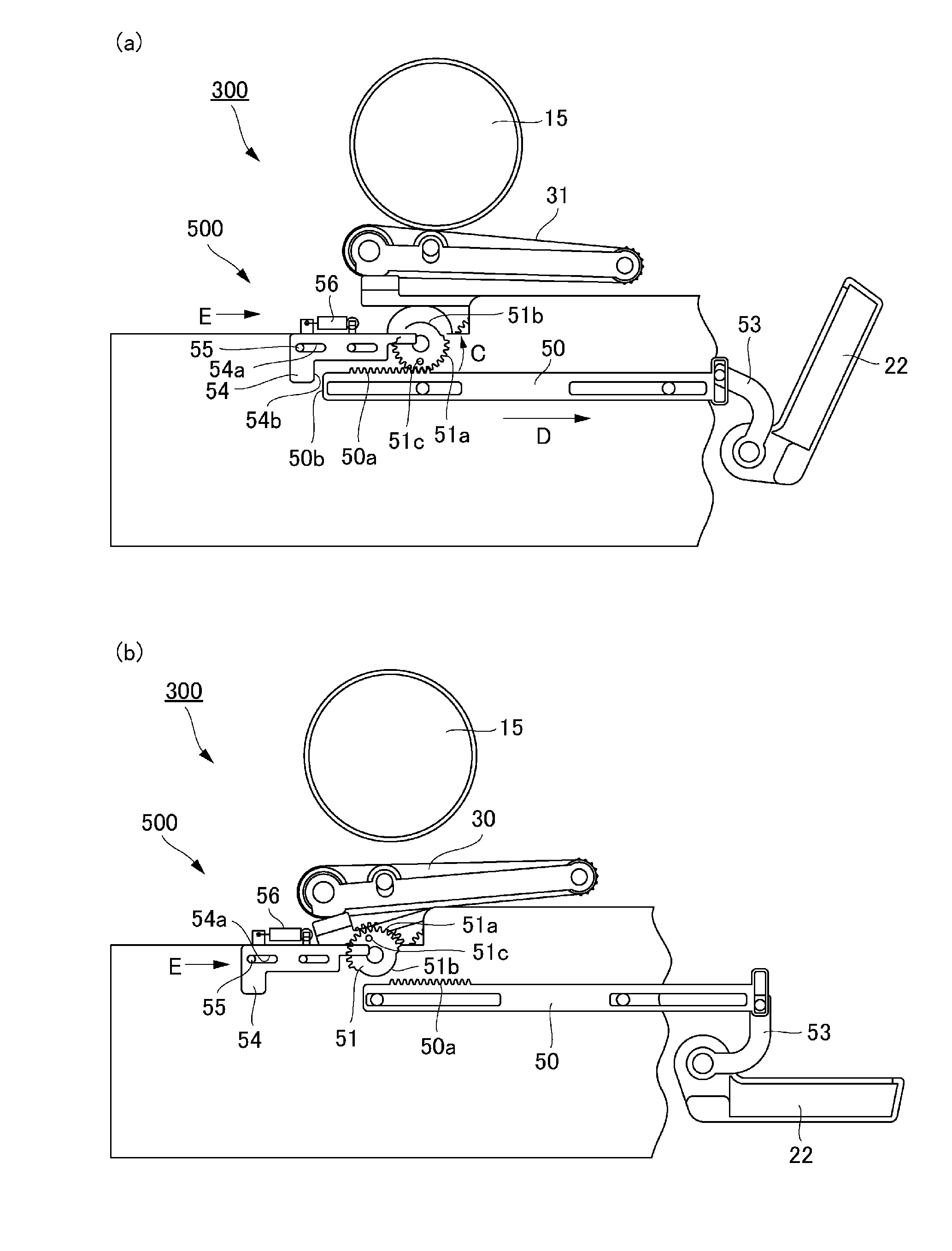
[0068]A handle-interrelated driving portion 300a in this embodiment includes a slide rack 60 which is slidably supported and which is moved in interrelation with the rotation operation of the locking handle 22, and includes a gear having partly omitted teeth 61 rotatable integrally with the cam shaft 41. The slide rack 60 is moved in the arrow D direction with the rotation of the locking handle 22 when the releasing op...

third embodiment

[0079]Third Embodiment of the present invention will be described with reference to FIG. 11 to FIG. 13. In the case of this embodiment, the rotation stopping mechanism for the transfer belt moving mechanism is different from that in the First Embodiment described above. Other constitutions and actions are the same as those in the First Embodiment and therefore in the following, redundant description and illustration are omitted or simplified and repeated reference numeral or symbols and repeated names are used as they are, and a different portion will be principally described.

[0080]A handle-interrelated driving portion 300b includes a slide rack 70 which is slidably supported and which is moved in interrelation with the rotation operation of the locking handle 22, and includes a gear having partly omitted teeth 71 rotatable integrally with the cam shaft 41. The gear having partly omitted teeth 71 includes a gear portion 71a and a non-toothed portion 71b.

[0081]Further, also in this ...


PUM


Abstract

An image forming apparatus includes an image bearing member forming a toner image, a belt member transferring the toner image, a cam transiting the belt member and the image bearing member between a contact state and a spaced state, and an operating lever for moving the belt member and the image bearing member between the contact state and the spaced state. In addition, a first member has a first engaging portion that moves in interrelation with movement of the cam and transmits a driving force of moving the operating lever to the cam, and a second member has a second engaging portion which engages with the first engaging portion and slidably movable to the first engaging portion. A third member regulates movement of the cam by abutting the second member when the operating lever is moved.

Description

FIELD OF THE INVENTION AND RELATED ART[0001]In an image forming apparatus, such as a copying machine or a printer, to which electrophotography is applied, as a form of a transfer means, a transfer device of a belt transfer type in which a toner image on an image bearing member is transferred onto a sheet while attracting and conveying the sheet by a transfer belt which is a belt member has been used. The image forming apparatus including the transfer device of the belt transfer type includes a transfer belt moving mechanism, using a motor, a solenoid or the like as a driving source, for moving the transfer belt toward and away from the image bearing member with desired timing such as an image forming operation or during jam occurrence.[0002]On the other hand, in order to facilitate jam clearance or a maintenance operation, an image forming apparatus including a conveying unit, on which a transfer device, a fixing device and the like which are provided in a conveying path are mounted...

Claims


Application Information

Patent Timeline
Patent Type & Authority Patents(United States)
IPC IPC(8): G03G21/16
CPCG03G21/168G03G21/1647
Inventor ONODERA, SHINICHIUCHIBE, TOSHIYA
Owner CANON KK
Why Eureka
Try Eureka