Mobility pattern based preemptive load balancing

Active Publication Date: 2016-01-26
SPRINT SPECTRUM LLC
View PDF5 Cites 5 Cited by
  • Summary
  • Abstract
  • Description
  • Claims
  • Application Information

AI Technical Summary

Problems solved by technology

This is the so-called

Method used


Image

  • Mobility pattern based preemptive load balancing
  • Mobility pattern based preemptive load balancing
  • Mobility pattern based preemptive load balancing

Examples


Embodiment Construction

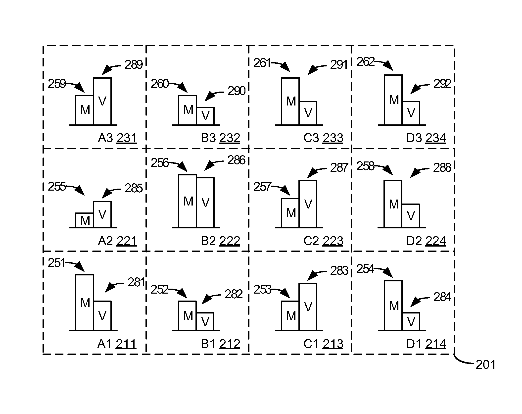
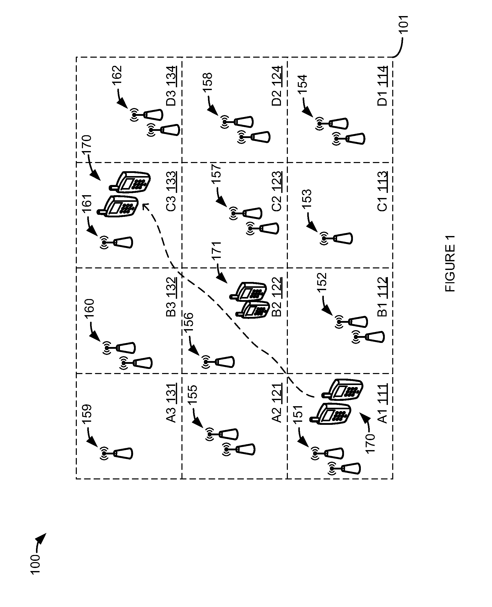
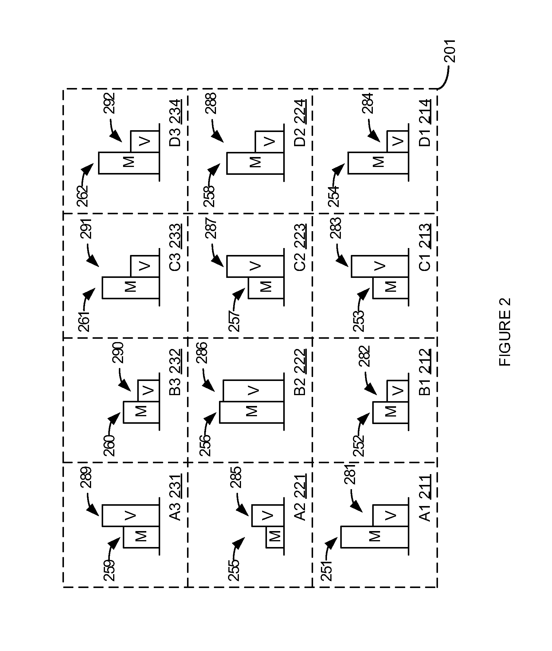
[0012]In an embodiment, a given geographic area (e.g., market, city, tracking area) is divided into a map grid of subareas (e.g., 1 mile on a side squares). For each grid square, traffic volume and mobility are measured over a selected time interval (e.g., morning commute—7 to 9 a.m.) Adjacent grid squares of high mobility indicate a large number of wireless devices traveling the same route (e.g., an interstate highway). Grid squares with high volume indicate potential loading problems. Correlating the mobility map grid squares with the corresponding volume map grid squares indicate areas where problems are likely to be caused by wireless devices that are moving during the selected time period.

[0013]To reduce problems caused by these moving wireless devices, stationary wireless devices using an access node in the problem area are identified before the selected time period (e.g., 30 minutes before commuting time). These stationary wireless devices are handed over to a reserved freque...


PUM


Abstract

Maps of high wireless device movement and high wireless device traffic are created. These maps are correlated over selected periods of time to determine when, and where, large numbers of wireless devices are both moving and creating problematic traffic. Stationary wireless devices using an access node in the problem area are identified before the selected time period (e.g., 30 minutes before commuting time). These stationary wireless devices are handed over to a reserved frequency band. During the selected time period, wireless devices requesting access in the problem area are denied access using the reserved frequency band and are instead forced to use another frequency band.

Description

TECHNICAL BACKGROUND[0001]Wireless communication may be used as a means of accessing a network. Wireless communication has certain advantages over wired communications for accessing a network. One of those advantages is a lower cost of infrastructure to provide access to many separate locations or addresses compared to wired communications. This is the so-called “last mile” problem. Another advantage is mobility. Wireless communication devices, such as cell phones, are not tied by wires to a fixed location. To use wireless communication to access a network, a customer needs to have at least one transceiver in active communication with another transceiver that is connected to the network.[0002]To facilitate wireless communications, the Institute of Electrical and Electronics Engineers (IEEE) has promulgated a number of wireless standards. These include the 802.11 (WiFi) standards and the 802.16 (WiMAX) standards. Likewise, the International Telecommunication Union (ITU) has promulgat...

Claims


Application Information

Patent Timeline
IPC IPC(8): H04W36/00H04W28/02H04W4/021
CPCH04W28/0226H04W72/0453H04L47/28H04W36/32H04W36/06H04W36/22H04W4/021H04W72/51
Inventor VIVANCO, DANIELSITARAM, KRISHNALIU, CHUNMEI
Owner SPRINT SPECTRUM LLC
Why Eureka
Try Eureka