Pacemakers and pacemaker leads

a pacemaker and lead technology, applied in the field of pacemakers and lead leads, can solve the problems of low mechanical strength of the electrode line, difficult to remove the electrode line from the organ or tissue of human beings after therapy,

Active Publication Date: 2016-02-02
TSINGHUA UNIV +1
View PDF30 Cites 0 Cited by
  • Summary
  • Abstract
  • Description
  • Claims
  • Application Information

AI Technical Summary

Benefits of technology

[0060]The pacemaker has the following advantages. When the electrode line with the radioactive particles is implanted into the tissue of the body, the radioactive particles can prevent an excessive fibrotic tissue growth on the electrode line. Thus, the electrode line of the pacemaker can be easily removed from the tissue after therapy. The radioactive particles is distributed in the interspaces of the carbon nanotube structure or filled in the hollow structure of carbon nanotubes of the carbon nanotube structure to form the shielding layer. Thus, the conductivity of the electrode line can be increased. The carbon nanotube wires or the carbon nanotube films are closely and uniformly combined to an outer surface of the insulating layer by van der Waals force to from the shielding layer. Thus, the toughness and mechanical strength of the electrode line can be increased. The conductor of the electrode line is composed of carbon nanotubes, thus, the conductor has a good conductivity. The efficiency of the pacemaker can be improved.

Problems solved by technology

However, when the pacemaker is implanted into the organ or the tissue of human, an excessive fibrotic tissue growth can take place on the electrode line, thus making the electrode line difficult to be removed from the organ or the tissue of human beings after therapy.
Additionally, a conductor in the electrode line is made of metal or alloy and the conductor has small diameter, so a mechanical strength of the electrode line is low.

Method used


Image

  • Pacemakers and pacemaker leads
  • Pacemakers and pacemaker leads
  • Pacemakers and pacemaker leads

Examples


Embodiment Construction

[0019]The disclosure is illustrated by way of example and not by way of limitation in the figures of the accompanying drawings in which like references indicate similar elements. It should be noted that references to “an” or “one” embodiment in this disclosure are not necessarily to the same embodiment, and such references mean at least one.

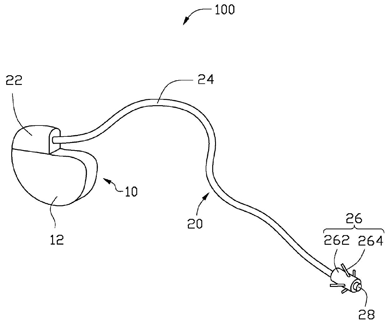
[0020]Referring to FIG. 1, a pacemaker 100 of one embodiment is provided. The pacemaker 100 can be a brain pacemaker or a cardiac pacemaker. The pacemaker 100 is a unipolar pacemaker. The pacemaker 100 includes a pulse generator 10 and an electrode line 20 electrically connected to the pulse generator 10. The pulse generator 10 can generate electrical pulse signals traveling through the electrode line 20 to stimulate the brain tissue or the heart tissue.

[0021]The pulse generator 10 includes a shell 12, a power source (not show) and a control circuit (not show). The power source and the control circuit are packaged in the shell 12. The power sourc...


PUM


Abstract

A pacemaker is provided. The pacemaker includes a pulse generator and an electrode line connecting with the pulse generator. The electrode line includes a conductor, an insulation layer and a shielding layer. The insulation layer is located on an outer surface of the conductor. The shielding layer is located on an outer surface of the first insulation layer. The shielding layer is a carbon nanotube structure having a plurality of radioactive particles therein.

Description

RELATED APPLICATIONS[0001]This application claims all benefits accruing under 35 U.S.C. §119 from China Patent Application No. 201110333502.2, filed on Oct. 28, 2011 in the China Intellectual Property Office, the disclosure of which is incorporated herein by reference. This application is related to common-assigned applications entitled, “ELECTRODE LEAD OF PACEMAKER AND PACEMAKER USING THE SAME,” Ser. No. 13 / 527,820, filed on Jun. 20, 2012, US Patent Application Publication No. 2013 / 0110215; “METHOD FOR MAKING PACEMAKER ELECTRODE LEAD,” Ser. No. 13 / 527,780, filed on Jun. 20, 2012, US Patent Application Publication No. 2013 / 0104396; “ELECTRODE LEAD OF PACEMAKER AND PACEMAKER USING THE SAME,” Ser. No. 13 / 527,782, filed on Jun. 20, 2012, U.S. Pat. No. 8,825,178; “ELECTRODE LEAD OF PACEMAKER AND PACEMAKER,” Ser. No. 13 / 527,784, filed on Jun. 20, 2012, US Patent Application Publication No. 2013 / 0109986; “PACEMAKERS AND PACEMAKER LEADS,” Ser. No. 13 / 527,792, filed on Jun. 20, 2012, US Pat...

Claims


Application Information

Patent Timeline
Patent Type & Authority Patents(United States)
IPC IPC(8): A61N1/05A61N5/10A61N1/08B82Y5/00B82Y30/00
CPCA61N1/056A61N1/05A61N5/1001A61N2001/086B82Y5/00B82Y30/00A61N1/086
Inventor FENG, CHENQIAN, LIFAN, LIZHAO, WEN-MEILIU, LIANGWANG, YU-QUAN
Owner TSINGHUA UNIV
Why Eureka
Try Eureka