Shifting procedure for powersplit systems

a technology of power transmission and power splitter, which is applied in the direction of fluid gearing, gearing control, climate sustainability, etc., can solve the problems of typical torque interruption of vehicles, and achieve the effect of increasing the range of operating speeds of vehicles, reducing torque interruption, and increasing fuel efficiency

Active Publication Date: 2016-02-02
DANA BELGIUM
View PDF27 Cites 0 Cited by
  • Summary
  • Abstract
  • Description
  • Claims
  • Application Information

AI Technical Summary

Benefits of technology

[0006]Presently provided by the invention, a method for shifting a powersplit transmission between modes of operation that minimizes torque interruption, increases a fuel efficiency of a vehicle, and increases a range of operating speeds of the vehicle the powersplit transmission is incorporated in, has surprisingly been discovered.
[0007]In one embodiment, the present invention is directed to a method for shifting a transmission. The transmission includes a mechanical portion drivingly engaged with an output of the transmission, a hydraulic portion, a primary clutch, and a secondary clutch. The primary clutch is disposed between the hydraulic portion and the output of the transmission and the secondary clutch is disposed between the hydraulic portion and the mechanical portion. The method comprises the steps of providing the transmission capable of operating in a hydrostatic power transmission mode or a blended hydrostatic and mechanical power transmission mode; placing the transmission in the hydrostatic power transmission mode; reducing an amount of engagement of the primary clutch, thereby adjusting a torque applied to the output; adjusting a rotational speed of the hydraulic portion to facilitate driving engagement between the hydraulic circuit and mechanical portion, thereby adjusting a torque applied to the output; increasing an amount of engagement of the secondary clutch, thereby adjusting a torque applied to the output of the transmission; and engaging the secondary clutch and disengaging the primary clutch.

Problems solved by technology

When the powersplit transmission changes from the hydrostatic power transmission mode to the blended hydrostatic and mechanical power transmission mode, the vehicle typically experience a torque interruption.

Method used


Image

  • Shifting procedure for powersplit systems
  • Shifting procedure for powersplit systems
  • Shifting procedure for powersplit systems

Examples


Embodiment Construction

[0021]It is to be understood that the invention may assume various alternative orientations and step sequences, except where expressly specified to the contrary. It is also to be understood that the specific devices and processes illustrated in the attached drawings, and described in the following specification are simply exemplary embodiments of the inventive concepts defined herein. Hence, specific dimensions, directions or other physical characteristics relating to the embodiments disclosed are not to be considered as limiting, unless expressly stated otherwise.

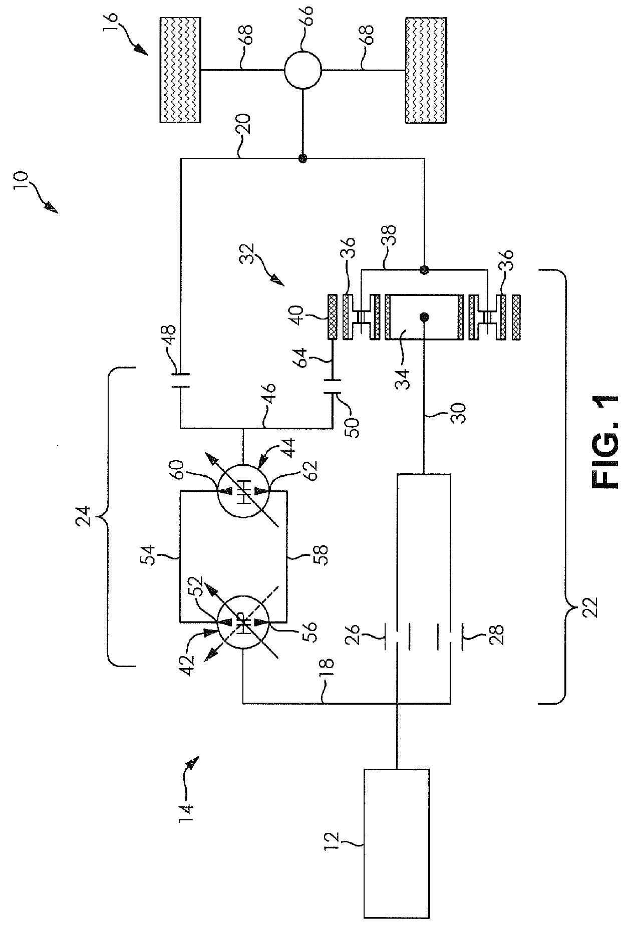
[0022]FIG. 1 schematically illustrates a driveline 10 for a vehicle. The driveline 10 comprises a power source 12, a powersplit transmission 14, and a vehicle output 16.

[0023]The power source 12 is drivingly engaged with an input 18 of the powersplit transmission 14. An output 20 of the powersplit transmission 14 is drivingly engaged with the vehicle output 16.

[0024]The power source 12 applies power to the input 18 of the ...


PUM


Abstract

A method for shifting a transmission capable of operating in a hydrostatic power transmission mode or a blended hydrostatic and mechanical power transmission mode is provided. The transmission includes a mechanical portion and a hydraulic portion. The method comprises the steps of placing the transmission in the hydrostatic power transmission mode, reducing an amount of engagement of a primary clutch, adjusting a rotational speed of the hydraulic portion, increasing an amount of engagement of a secondary clutch, and engaging the secondary clutch and disengaging the primary clutch. The method for shifting the transmission minimizes torque interruption, increases a fuel efficiency of a vehicle, and increases a range of operating speeds of the vehicle the transmission is incorporated in.

Description

CLAIM OF PRIORITY[0001]The present application claims priority to and incorporates by reference U.S. Provisional Application No. 61 / 568,687 filed Dec. 9, 2011, entitled “Shifting Procedure for Powersplit Systems.”BACKGROUND OF THE INVENTION[0002]The present invention generally relates to power transmission systems. More particularly, this invention relates to a powersplit transmission for a vehicle, in which the powersplit transmission may be operated in a hydrostatic power transmission mode or a blended hydrostatic and mechanical power transmission mode.[0003]Vehicles that incorporate the powersplit transmission, such as earth moving machinery, industrial equipment, and others may be operated in the hydrostatic power transmission mode or the blended hydrostatic and mechanical power transmission mode. In the hydrostatic power transmission mode, a speed of the vehicle or a motion of a hydraulically operated attachment coupled to the vehicle may be precisely controlled. Such a mode of...

Claims


Application Information

Patent Timeline
Patent Type & Authority Patents(United States)
IPC IPC(8): B60W10/02F16H61/472F16H47/04
CPCB60W10/02F16H47/04Y02T10/76Y10T477/6425Y02T10/60
Inventor VERSTEYHE, MARK, R., J.
Owner DANA BELGIUM
Why Eureka
Try Eureka