Vehicle power supply apparatus

Inactive Publication Date: 2011-08-18
FUJI JUKOGYO KK
View PDF2 Cites 20 Cited by
  • Summary
  • Abstract
  • Description
  • Claims
  • Application Information

AI Technical Summary

Benefits of technology

[0011]According to the present invention, by switching the switch provided between the first power supply system and the second power supply system to the disconnected state, the generation voltage of the power gener

Problems solved by technology

Although it is possible to secure a large storage capacity with a lead storage battery, the battery deteriorates rapidly through charging and discharging.
Hence, in a vehicle installed with a lead storage battery, charging and discharging of the lead storage battery is prevented by driving an alternator (a power generator) to generate power at all times. However, when the alternator is driven constantly, an engine load increases, leading to a reduction in fuel efficiency.
However, in the vehicle described in Japanese Unexamined Patent Application Publication No. 2004-225649, the electrical equipment is connected

Method used


Image

  • Vehicle power supply apparatus
  • Vehicle power supply apparatus
  • Vehicle power supply apparatus

Examples


Embodiment Construction

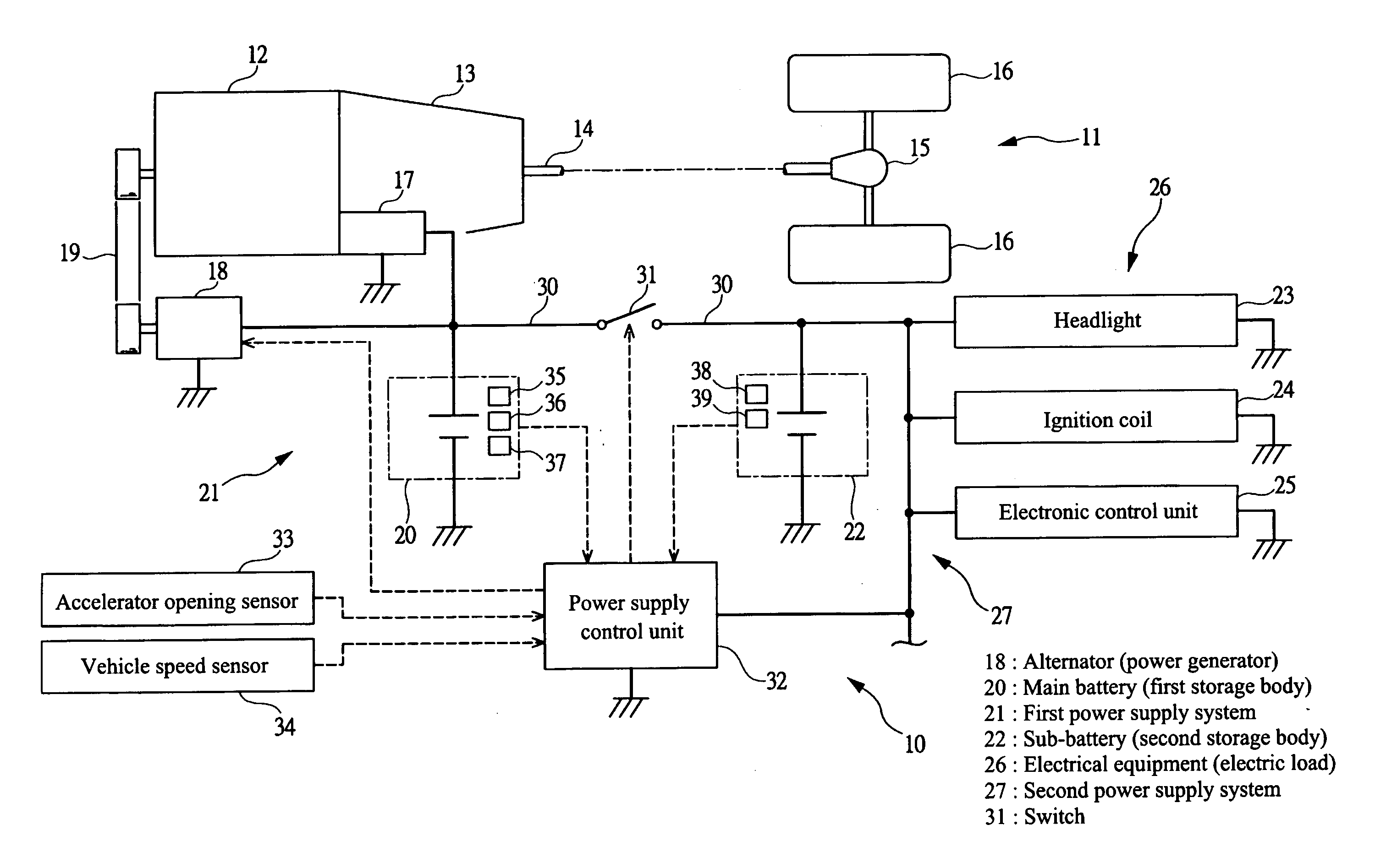
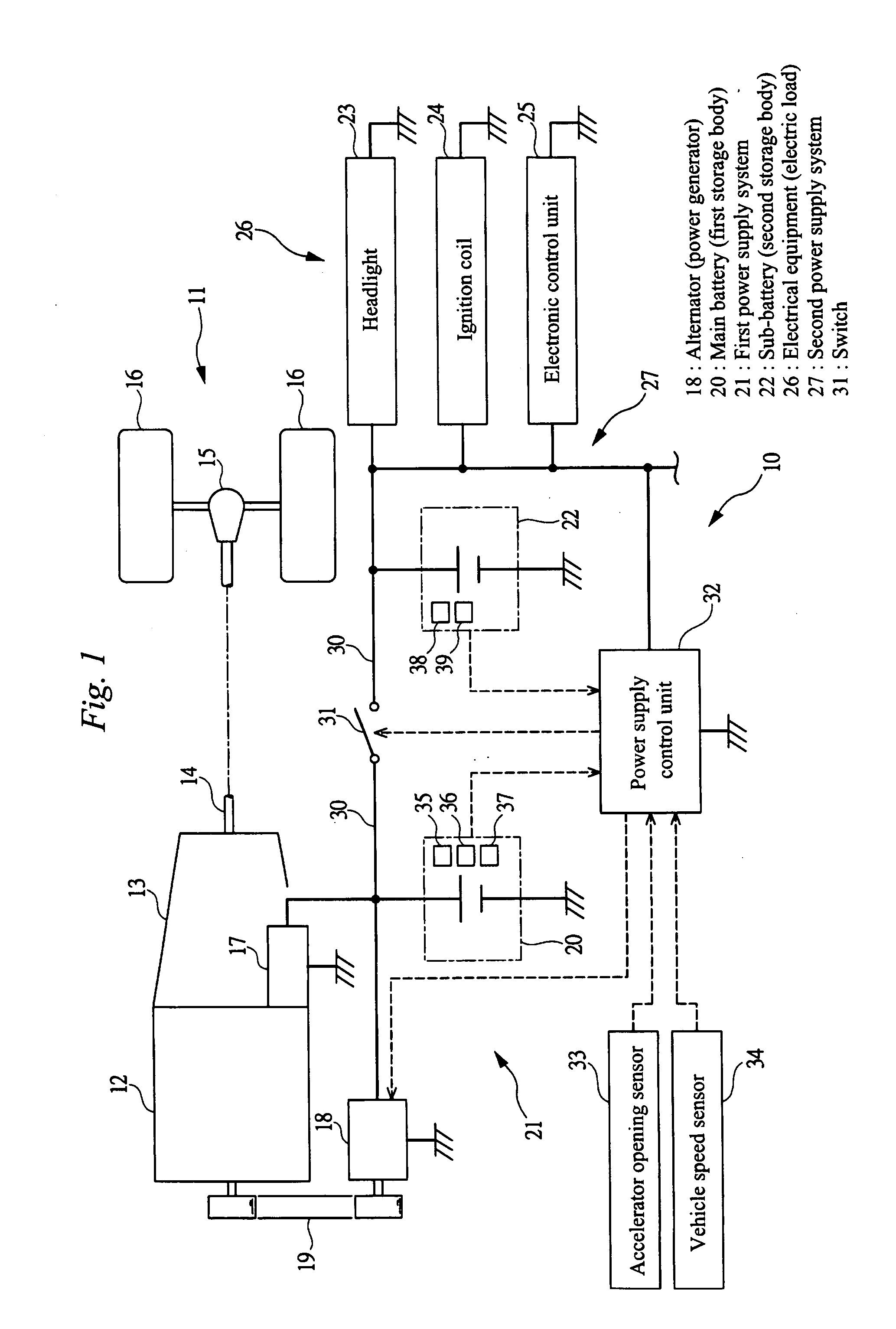
[0020]Embodiments of the present invention will be described in detail below on the basis of the drawings. FIG. 1 is a schematic view showing the constitution of a vehicle 11 including a vehicle power supply apparatus 10 according to an embodiment of the present invention. As shown in FIG. 1, the vehicle 11 is installed with an engine 12 and a transmission 13. Drive wheels 16 are coupled to an output shaft 14 of the transmission 13 via a differential mechanism 15. Further, a starter motor 17 is attached to the engine 12. Furthermore, an alternator 18 serving as a power generator is coupled to the engine 12 via a drive belt 19. Note that the vehicle 11 shown in the drawing is a so-called micro-hybrid vehicle installed with a low voltage regeneration system employing the alternator 18. When depression of an accelerator pedal is released such that the vehicle decelerates, the alternator 18 is driven to generate power, whereby kinetic energy of the vehicle 11 is actively converted into ...


PUM


Abstract

A first power supply system is constituted by an alternator and a main battery while a second power supply system is constituted by electrical equipment and a sub-battery. Further, a switch is provided between the first power supply system and the second power supply system. During vehicle deceleration, the switch is switched to a disconnected state, whereby the first power supply system and the second power supply system are disconnected. As a result, a generation voltage of the alternator can be raised, enabling an increase in the generation amount, without applying an excessive voltage to the electrical equipment. Hence, the main battery can be charged sufficiently during deceleration, and therefore the alternator can be halted during acceleration and steady travel. Furthermore, by halting the alternator, an engine load can be reduced, and as a result, an improvement in the fuel efficiency of the vehicle can be achieved.

Description

CROSS-REFERENCE TO RELATED APPLICATIONS[0001]The present application claims priority from Japanese Patent Application No. 2010-028888, filed on Feb. 12, 2010, and is hereby incorporated by reference in its entirety.BACKGROUND OF THE INVENTION[0002]1. Field of the Invention[0003]The present invention relates to a vehicle power supply apparatus installed in a vehicle.[0004]2. Description of the Related Art[0005]In a conventional vehicle, power is typically supplied to electrical equipment by the use of a lead storage battery. Although it is possible to secure a large storage capacity with a lead storage battery, the battery deteriorates rapidly through charging and discharging. Hence, in a vehicle installed with a lead storage battery, charging and discharging of the lead storage battery is prevented by driving an alternator (a power generator) to generate power at all times. However, when the alternator is driven constantly, an engine load increases, leading to a reduction in fuel ef...

Claims


Application Information

Patent Timeline
IPC IPC(8): B60L1/00
CPCB60L7/10B60R25/00H01M10/44Y02T10/7005H02J7/0054H02J7/1423H02J7/1438H01M10/48H02J7/342Y02T10/70Y02E60/10
Inventor KOMURO, MASAKISATO, YUTAKAONO, MIKIO
Owner FUJI JUKOGYO KK
Why Eureka
Try Eureka