Drive control device of hybrid vehicle

a technology of driving control and hybrid vehicles, which is applied in the direction of vehicle position/course/altitude control, process and machine control, instruments, etc., can solve the problems of increasing electric loss, achieve high control accuracy, prevent overdischarge or overloading of batteries, and improve the control accuracy of the soc of batteries

Active Publication Date: 2014-03-20
SUZUKI MOTOR CORP
View PDF1 Cites 24 Cited by
  • Summary
  • Abstract
  • Description
  • Claims
  • Application Information

AI Technical Summary

Benefits of technology

[0029]As described above, according to the present invention, there is provided a drive control device of a hybrid vehicle including: an internal combustion engine that includes an output shaft; a driving shaft that is connected to a drive wheel; first and second motor generators; a differential gear mechanism that includes four rotating components connected to a plurality of the motor generators, the driving shaft, and the internal combustion engine; an accelerator opening degree detecting means that detects the accelerator opening degree; a vehicle speed detecting means that detects a vehicle speed; a battery charge state detecting means that detects a charge state of a battery; a target driving power setting means that sets target driving power based on the accelerator opening degree that is detected by the accelerator opening degree detecting means and the vehicle speed detected by the vehicle speed detecting means; a target charge / discharge power setting means that sets target charge / discharge power based on at least the charge state of the battery that is detected by the battery charge state detecting means; a target engine power calculating means that calculates target engine power based on the target driving power of the target driving power setting means and the target charge / discharge power of the target charge / discharge power setting means; a target engine operating point setting means that sets a target engine operating point based on the target engine power and total system efficiency; a motor torque instruction value calculating means that sets torque instruction values of the plurality of the motor generators; an electric power loss predicting means that calculates estimated power that is an electric power loss based on the vehicle speed and the target driving force; an electric power upper limit / lower limit value calculating means that sets an electric power upper limit and an electric power lower limit for limiting input / output electric power for the battery based on the estimated power that is the electric power loss and battery state parameters; and a target electric power calculating means that calculates target electric power based on a difference between the target engine power and the target driving power calculated at the target engine operating point and, when the target electric power comes off a range set by the electric power upper limit and the electric power lower limit, limits the target electric power to the electric power upper limit or the electric power lower limit, wherein the motor torque instruction value calculating means calculates torque instruction values of the plurality of the motor generators using a torque balance equation including the target engine torque acquired at the target engine operating point and an electric power balance equation including the target electric power.
[0030]Accordingly, by limiting the input / output power in accordance with the state of the battery in consideration of the electric power losses of a plurality of motor generators, the charge / discharge electric power can be appropriately limited in a case where driving assistance is performed using the electric power of the battery, whereby overdischarge or overloading of the battery can be prevented.
[0031]In addition, the control accuracy of the SOC of the battery can be improved in consideration of the electric power losses of the plurality of motor generators.
[0032]Furthermore, since the control accuracy is high, a range near the limit value of the battery can be used, whereby the amount of regeneration at the time of deceleration can be increased.
[0033]In addition, both the target driving force of the motor generator and the charge / discharge near the target preventing overcharge / overdischarge of the battery can be secured in consideration of the operating point of the internal combustion engine.
[0034]Furthermore, after the target engine rotation speed is reset so as not to exceed the upper limit value of the target engine rotation speed, target electric power different from the target charge / discharge power is set based on the target engine rotation speed, and the driving forces of the plurality of motor generators are set based on the optimized target engine operating point and the optimal target electric power preventing overcharge / overdischarge, whereby the internal combustion engine is protected by limiting the engine rotation speed, and the driving force requested by the driver can be satisfied based on the power assistance using the electric power of the battery.

Problems solved by technology

However, although not as much as for the serial form, since an electric motor having relatively high torque is necessary for acquiring sufficient driving-shaft torque, and the amount of transmission and reception of electric power between the power generator and the electric motor increases in a low gear ratio region, the electric loss increases, and there is still a room for improvement.

Method used


Image

  • Drive control device of hybrid vehicle
  • Drive control device of hybrid vehicle
  • Drive control device of hybrid vehicle

Examples


embodiment

[0056]FIGS. 1 to 20 illustrate embodiments of the present invention.

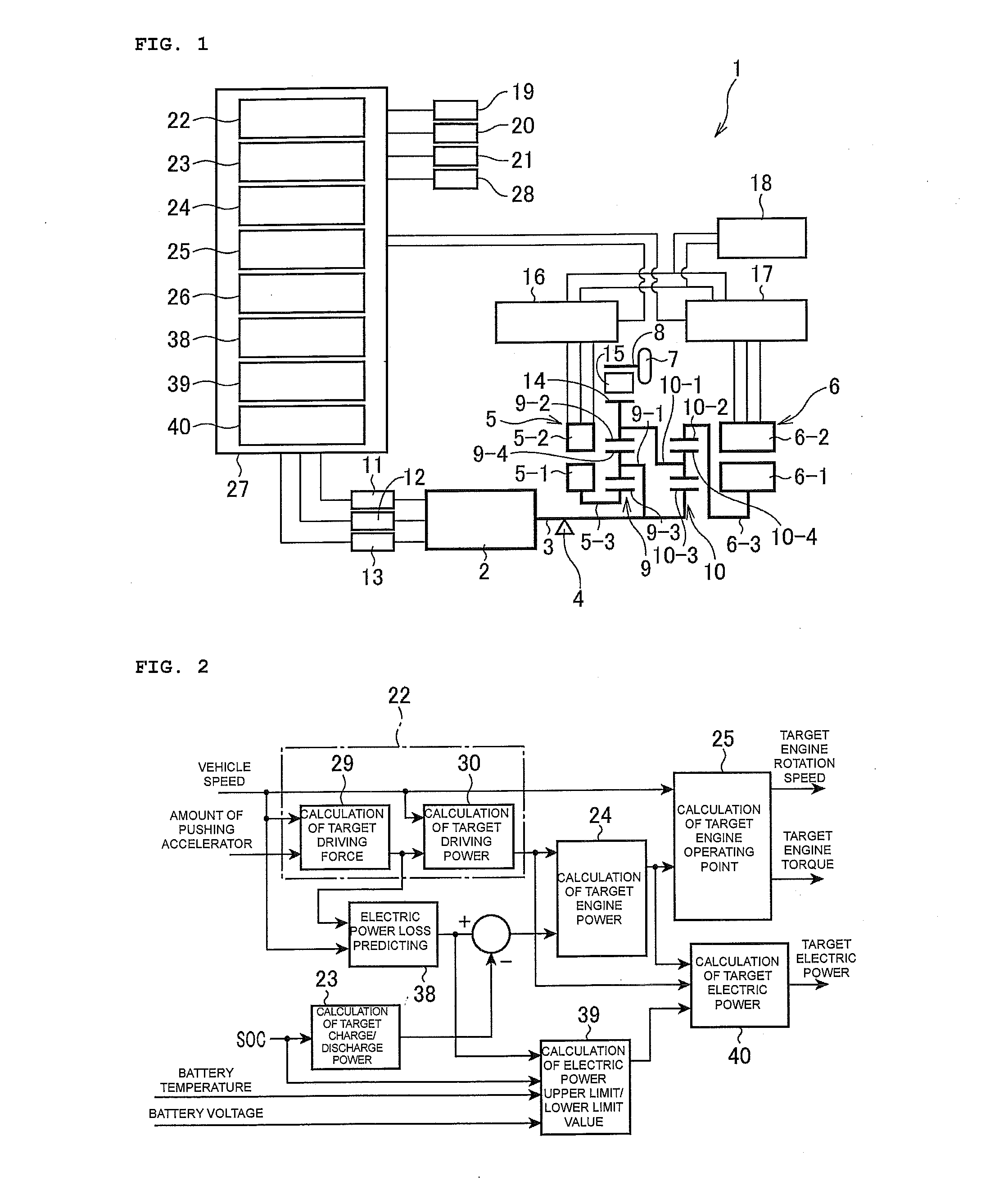
[0057]In FIG. 1, reference numeral 1 represents a drive control device of a hybrid vehicle not illustrated in the figure, in other words, a four-axis-type power input / output device to which the present disclosure is applied.

[0058]As illustrated in FIG. 1, in order to control the driving of the vehicle using outputs of an internal combustion engine (also represented as “E / G” or “ENG”) 2 and an electric motor, the drive control device (also referred to as a “power input / output device”) 1 of the hybrid vehicle includes: a first motor generator (also referred to as “MG1” or “first electric motor”) 5 and a second motor generator (also referred to as “MG2” or “second electric motor”) 6 that are connected to an output shaft 3 of the internal combustion engine 2 generating a driving force in accordance with combustion of fuel through a one-way clutch 4 as a driving system, generate driving forces based on electricity, and g...


PUM


Abstract

Objects of the present invention is to improve the control accuracy of the SOC of the battery in consideration of the electric power losses of a plurality of motor generators and, in accordance therewith, to secure the protection performance of the battery and to increase the energy recovery efficiency according to the regeneration. In a drive control device of a hybrid vehicle including a motor torque instruction value calculating means, an electric power loss predicting means, an electric power upper limit/lower limit value calculating means, and a target electric power calculating means are arranged, and the motor torque instruction value calculating means calculates torque instruction values of a plurality of motor generators using a torque balance equation including target engine torque required at a target engine operating point and an electric power balance equation including target electric power.

Description

TECHNICAL FIELD[0001]The present invention relates to a control device of a hybrid vehicle that includes a plurality of power sources, combines the power thereof using a differential gear mechanism, and inputs or outputs the power to a driving shaft, and more particularly, to a drive control device of a hybrid vehicle that improves the control accuracy of the SOC or prevents a battery from being excessively loaded by controlling the operating point and the motor torque of an engine in consideration of the electric power loss of a motor.BACKGROUND ART[0002]Conventionally, as a form of a hybrid vehicle including an electric motor and an internal combustion engine other than a serial form and a parallel form, as disclosed in U.S. Pat. Nos. 3,050,125, 3,050,138, 3,050,141, 3,097,572, and the like, there is a form in which the torque of the power of the internal combustion engine is converted by dividing the power of the internal combustion engine to a power generator and a driving shaft...

Claims


Application Information

Patent Timeline
Patent Type & Authority Applications(United States)
IPC IPC(8): B60W20/00B60W10/08B60W10/26B60W10/06B60L50/16
CPCB60W20/106B60W10/06Y10S903/93B60W10/26B60W10/08B60K6/445B60W20/00B60W30/18127B60W30/1882B60W2710/0666B60W2710/083B60W2710/242Y02T10/92B60W20/14B60W20/13Y02T10/62B60W20/11Y02T10/84
Inventor ITO, YOSHIKITAGAWA, MASAAKISAITO, MASAKAZUOHKUMA, HITOSHIHOSOE, YUKIHIRO
Owner SUZUKI MOTOR CORP
Why Eureka
Try Eureka