

Integrated steering gear and frame structure
a steering gear and integrated technology, applied in the direction of steering linkages, fluid steering, transportation and packaging, etc., can solve the problems of inconvenient management of tolerance, production and quality, physical distribution cost of each sub-frame and steering gear, etc., and achieve the effect of saving production cost and cos
- Summary
- Abstract
- Description
- Claims
- Application Information
AI Technical Summary
Benefits of technology
Problems solved by technology
Method used
Image

Examples
Embodiment Construction
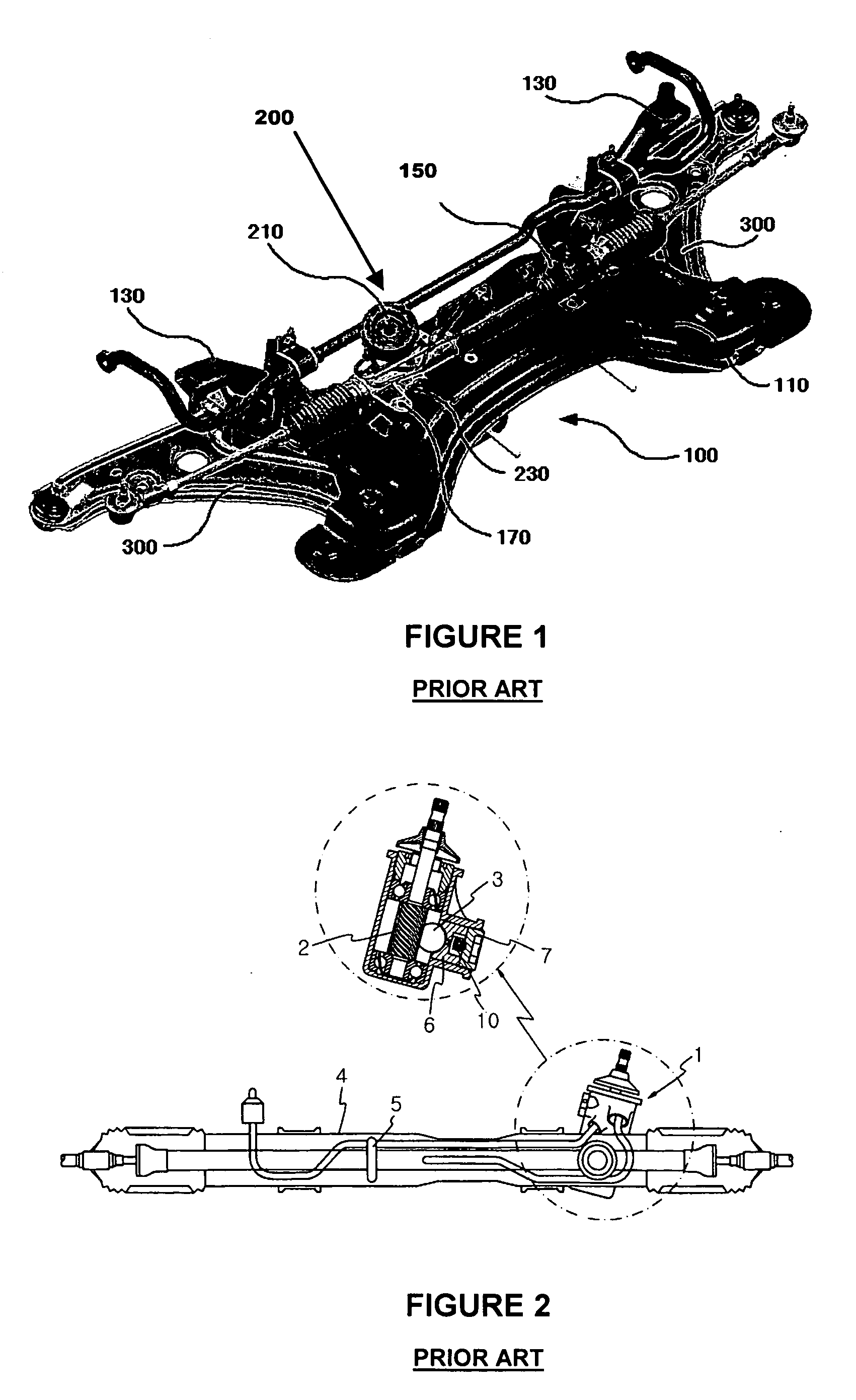
[0037] A preferred embodiment of the present invention will now be described with reference to the accompanying drawings. In the following description, same drawing reference numerals are used for the same elements even in different drawings. The matters defined in the description such as a detailed construction and elements of a circuit are nothing but the ones provided to assist in a comprehensive understanding of the invention. Thus, it is apparent that the present invention can be carried out without those defined matters. Also, well-known functions or constructions are not described in detail since they would obscure the invention in unnecessary detail.
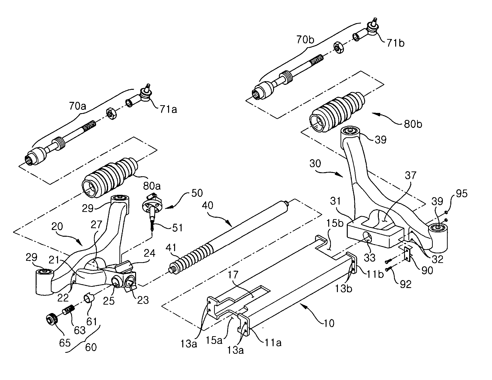
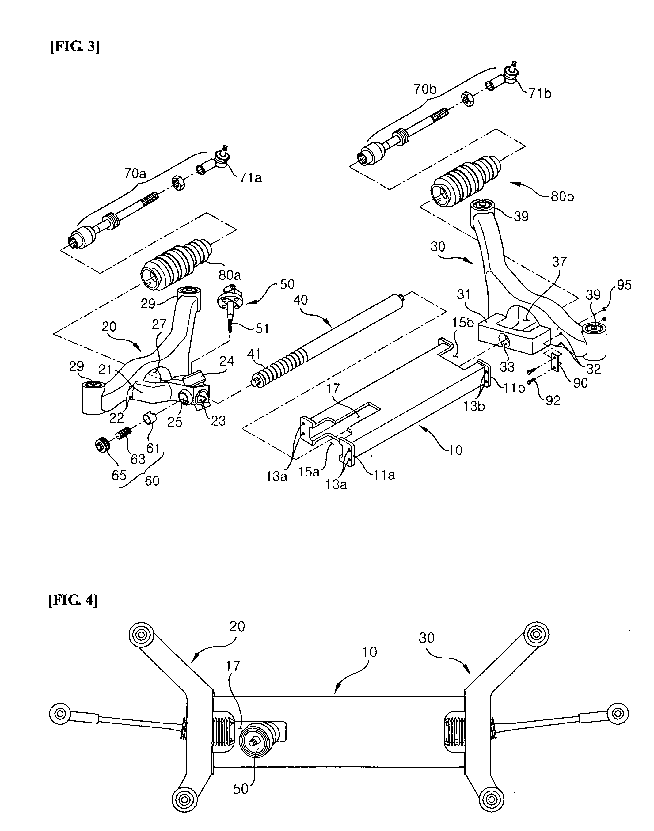
[0038]FIG. 3 is an exploded perspective view showing an integrated steering gear and frame structure according to a preferred embodiment of the invention, and FIG. 4 is an assembled plan view of the integrated steering gear and frame structure of FIG. 3.
[0039] As shown in FIGS. 3 and 4, the integrated steering gear and frame st...
PUM
 Abstract
Description
Claims
Application Information