Method and system for configuring a device for correcting the effect of a medium on a light signal, method, device and system for correcting said effect

a technology for light signals and devices, applied in the field of devices and systems for configuring devices for correcting the effect of mediums on light signals, can solve the problems of time-consuming techniques, and inability to efficiently and completely correct methods and systems, and achieve the effect of simple implementation, efficient and complete correction of the effect of the medium, and device configuration

Active Publication Date: 2016-02-02
CAILABS
View PDF2 Cites 37 Cited by
  • Summary
  • Abstract
  • Description
  • Claims
  • Application Information

AI Technical Summary

Benefits of technology

[0007]Another object of the present invention is to provide a method and a system making it possible to efficiently correct the effect of a medium on a light signal having propagated through said medium.
[0060]In a particular embodiment of the method according to the invention, the control light signal is sent through the output of the device, and is reflected at the input of the complex medium. Thus, the control light goes through the correcting device, the medium, the medium again and finally the correcting device again. After the configuration phase, the device corrects the effect of the medium. Additional small changes occurring in the medium can be corrected using the calibration method with the control light.

Problems solved by technology

Nowadays, there is no method or system to efficiently and completely correct the effect of a medium on light signal having propagated through said medium.
Such a technique is time consuming because it involves a series of measurements and needs an important computation power.
Moreover the calculation involved may introduce errors.

Method used


Image

  • Method and system for configuring a device for correcting the effect of a medium on a light signal, method, device and system for correcting said effect
  • Method and system for configuring a device for correcting the effect of a medium on a light signal, method, device and system for correcting said effect
  • Method and system for configuring a device for correcting the effect of a medium on a light signal, method, device and system for correcting said effect

Examples


Embodiment Construction

[0092]In the following specifications, elements common to several figures are referenced through a common identifier.

DETAILED DESCRIPTION OF THE INVENTION

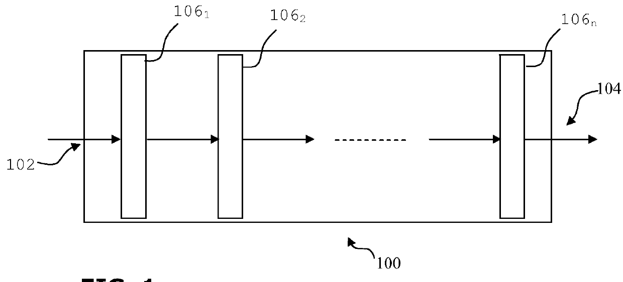
[0093]FIG. 1 schematically represents an example of a correcting device.

[0094]The correcting device 100 comprises at least one input 102 and at least one output 104.

[0095]Between the input 102 and the output 104, the correcting device 100 comprises several optical elements 1061-106n. Each optical element 106 has an adjustable spatial phase profile. For instance, each optical element 106 may be a spatial phase modulator (SLM) or a deformable mirror (DM). Each optical element 106 is separated from another optical element 106 by free space propagation and a lens (not represented), which perform an optical transform.

[0096]When configured, a disordered signal is input to the correcting device 100 and propagates across the optical elements 106 one after another. After the last optical element 106n, the disordered signal is corrected and ...


PUM

PropertyMeasurementUnit
spatial phase profileaaaaaaaaaa
phase delayaaaaaaaaaa
phaseaaaaaaaaaa

Abstract

A method and a system is provided for configuring a device for correcting the effect of a medium on a light signal having propagated through the medium, the device including at least one optical element whose phase profiles are individually adjustable. The configuring system and method include propagating a reference signal and a disordered signal obtained at the output of the medium through the correcting device. An interference parameter is measured and optimized by modifying the phase profile of each of the optical elements of the correcting device. A method and a system is also provided for correcting the effect of a medium on a light signal having propagated through the medium.

Description

FIELD OF THE INVENTION[0001]The present invention relates to a method and a system for configuring a device for correcting the effect of a medium on a light signal having propagated through said medium. The invention also relates to a method, a device and a system for correcting said effect.BACKGROUND OF THE INVENTION[0002]A light signal propagating through a medium, more particularly an optical medium, an optical fibre for instance, undergoes a modification applied by said medium to the signal. The signal at the output of the medium is a disordered or blurred version of the light signal input to the medium. The modification applied by the medium must be corrected in order to recover the information conveyed by the light signal.[0003]Nowadays, there is no method or system to efficiently and completely correct the effect of a medium on light signal having propagated through said medium.[0004]Some researchers focus on a technique consisting of computing the complete transmission matri...

Claims


Application Information

Patent Timeline
Patent Type & Authority Patents(United States)
IPC IPC(8): G02B26/00G02F1/01G02B26/06
CPCG02F1/0121G02B26/06
Inventor MORIZUR, JEAN-FRANCOISBACHOR, HANSTREPS, NICOLAS
Owner CAILABS
Why Eureka
Try Eureka