Clamping structure for mounting reducer
a technology of reducer and mounting structure, which is applied in the direction of pipe supports, friction grip releasable fastenings, and fastening means, etc., can solve the problems of inconvenient separation or disassembly, and achieve the effect of quick and easy coupling, easy rotation and easy coupling
- Summary
- Abstract
- Description
- Claims
- Application Information
AI Technical Summary
Benefits of technology
Problems solved by technology
Method used
Image

Examples
first embodiment
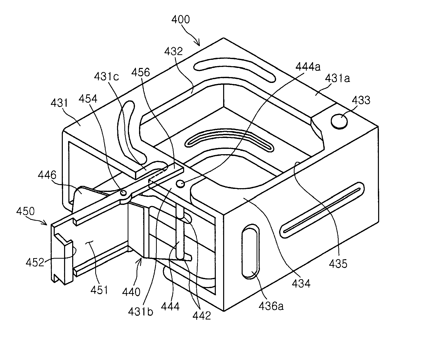
[0035]Referring to FIGS. 3 and 4, according to the invention, a clamp 400 includes a clamp body 431 that is formed at opposite sides thereof with a door connecting portion 431a and a latch member connecting portion 431b to form a rectangular shape with one open side, and a clamp door 434 that can be rotated about a hinge pin 433 formed at the door connecting portion 431a when a latch member 450 is released. According to this embodiment, the clamp 400 may be moved to a desired place, with a support frame 100 inserted into one side of the clamp body 431.
[0036]The clamp body 431 and the clamp door 434 are formed with a clamp groove 432 and a coupling groove 435, respectively, to define a space capable of receiving a body 222 of a sprinkler 200 when the body 222 is inserted into the clamp. Thus, in order to provide a clamping state between the clamp 400 and the sprinkler 200, the body 222 of the sprinkler 200 is inserted into the clamp body 431 in an opening / closing direction of the cla...
second embodiment
[0045]FIG. 5 is a perspective view of a clamping structure for mounting a reducer for sprinklers according to the present invention.
[0046]The latch member according to this embodiment has the same fundamental structure as that of the latch member shown in FIG. 3 and FIG. 4, and thus will be described using the same terms and reference numerals.
[0047]Referring to FIG. 5, according to a second embodiment of the invention, a clamp 400 includes a clamp body 431 that is formed at opposite sides thereof with a door connecting portion 431a and a latch member connecting portion 431b to form a rectangular shape with one open side, and a clamp door 434 that can be rotated about a hinge pin 433 formed at the door connecting portion 431a when a latch member 450 is released. According to this embodiment, the clamp 400 may be moved to a desired place, with a support frame 100 inserted into one side of the clamp body 431.
[0048]The clamp body 431 and the clamp door 434 are formed with a clamp groov...
third embodiment
[0051]FIG. 6 is a perspective view of a clamping structure for mounting a reducer for sprinklers according to the present invention.
[0052]As shown in FIG. 6, according to a third embodiment of the invention, a clamp 600 includes a clamp body 631 that is formed at opposite sides thereof with a door connecting portion 631a and a latch member connecting portion 631b to form a rectangular shape with one open side, and a clamp door 634 that can be rotated about a hinge pin 633 formed at the door connecting portion 631a when a latch member 650 is released. In this structure, the clamp 600 may be moved to a desired place, with a support frame 100 inserted into one side of a clamp body 631. Here, the door connecting portion 631a has a longer length than the latch member connecting portion 631b so as to avoid interference with a hinge 654 formed in the latch member 650 upon fastening of the clamp door 634, which will be described below.
[0053]The clamp body 631 and the clamp door 634 are form...
PUM
 Abstract
Description
Claims
Application Information
 - R&D Engineer
- R&D Manager
- IP Professional
- Industry Leading Data Capabilities
- Powerful AI technology
- Patent DNA Extraction
Browse by: Latest US Patents, China's latest patents, Technical Efficacy Thesaurus, Application Domain, Technology Topic.
© 2024 PatSnap. All rights reserved.Legal|Privacy policy|Modern Slavery Act Transparency Statement|Sitemap