Outboard motor and vessel

a technology for outboard motors and vessels, applied in the field of outboard motors, can solve the problems of decreasing the supply flow rate of cooling water to the cooling water passage, and achieve the effects of reducing the heat resistance of the exhaust passage, light weight, and reducing heat resistan

Active Publication Date: 2016-02-16
YAMAHA MOTOR CO LTD
View PDF8 Cites 1 Cited by
  • Summary
  • Abstract
  • Description
  • Claims
  • Application Information

AI Technical Summary

Benefits of technology

[0013]When an abnormality, such as clogging of the water inlet, etc., occurs in the cooling device, the supply flow rate of the cooling water to the cooling water passage decreases. In this state, the cooling water remaining inside the cooling water passage tends to flow down due to its own weight. The restriction valve restricts the flow of fluid from the exterior of the cooling water passage to the interior of the cooling water passage via the vent hole. The air outside the cooling water passage is thus unlikely to enter into the cooling water passage via the vent hole and the cooling water is unlikely to be discharged from the cooling water passage. The rate of discharge of the cooling water from the cooling water passage is thus decreased and the retention time of the cooling water inside the cooling water passage is lengthened. Lowering of the cooling ability is thus significantly reduced or prevented when an abnormality occurs in the cooling device. A temperature rise of the exhaust passage and the catalyst is thus significantly reduced or prevented.
[0035]With this arrangement of the present preferred embodiment of the present invention, the normally open solenoid valve is used as the restriction valve. The controller opens and closes the solenoid valve as the restriction valve based on the temperature of the engine. Specifically, the engine temperature is detected by the temperature detecting device and the detection value of the temperature detecting device is input into the controller. The controller closes the restriction valve when the engine temperature is not less than the predetermined value (for example, an overheating temperature). That is, when the engine temperature reaches the predetermined value due to an abnormality of the cooling device, the controller closes the restriction valve and maintains the state in which the restriction valve is closed until the engine temperature falls below the predetermined value. Therefore, when an abnormality of the cooling device occurs, the discharge of the cooling water from the cooling water passage is restricted and the lowering of the cooling ability is significantly reduced or prevented. A temperature rise of the exhaust passage and the catalyst is thus significantly reduced or prevented.

Problems solved by technology

When an abnormality, such as clogging of the water inlet, etc., occurs in the cooling device, the supply flow rate of the cooling water to the cooling water passage decreases.

Method used


Image

  • Outboard motor and vessel
  • Outboard motor and vessel
  • Outboard motor and vessel

Examples


Embodiment Construction

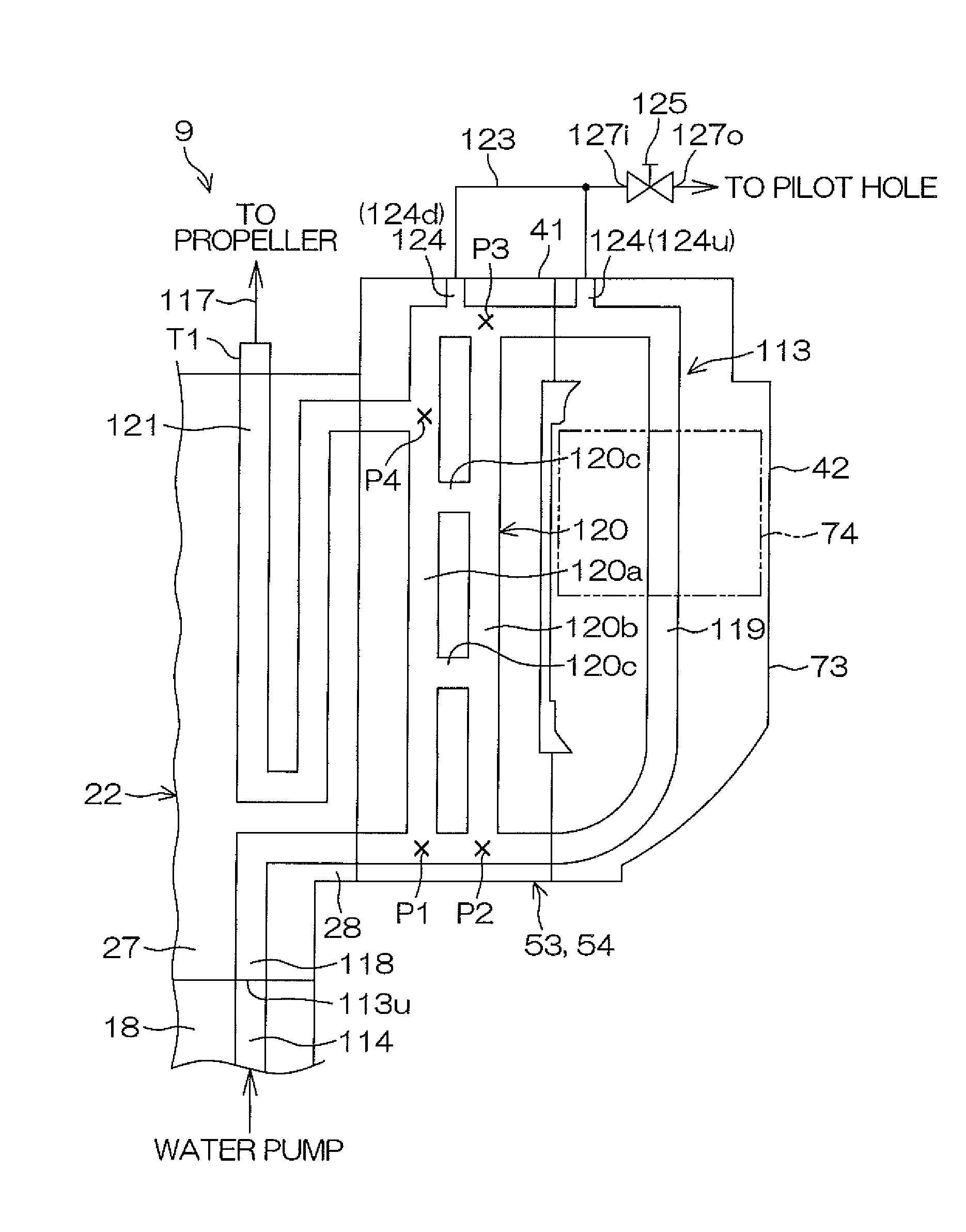
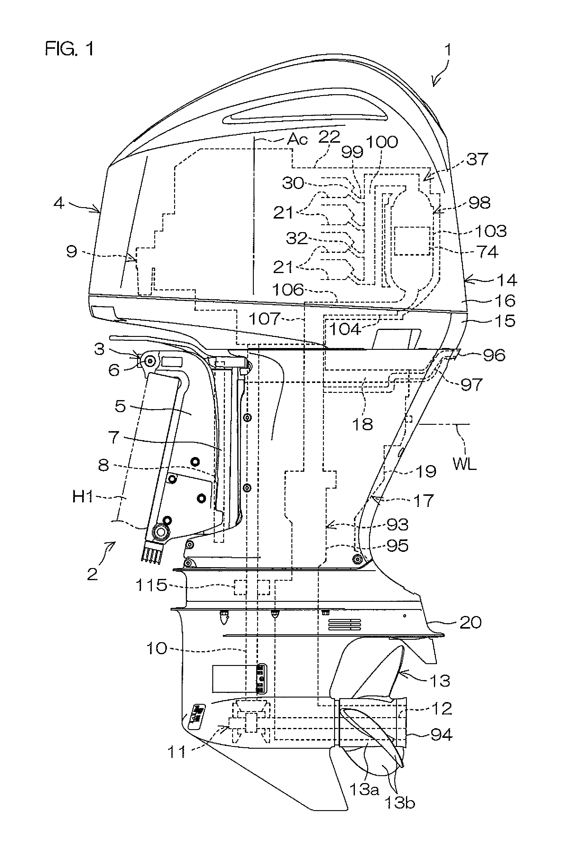
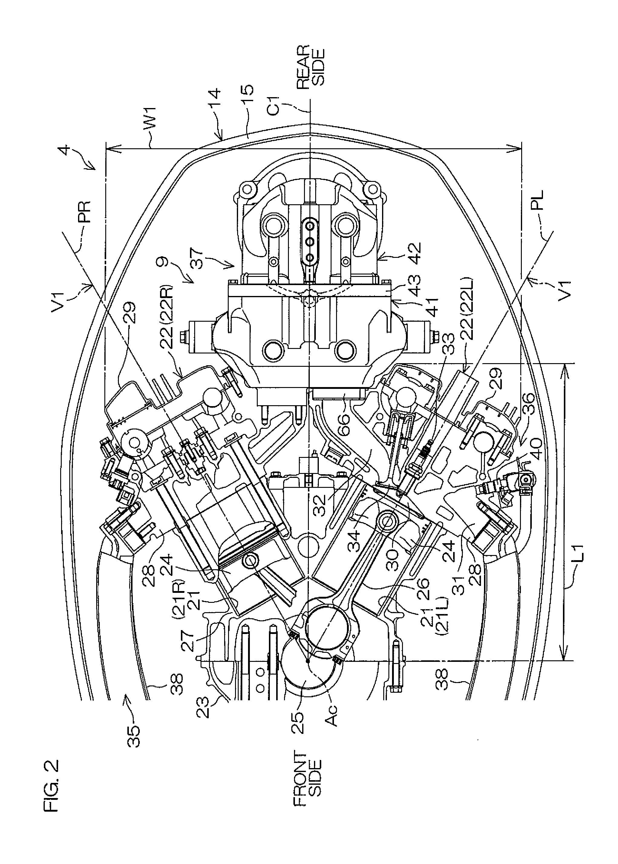
[0071]FIG. 1 is a schematic side view of a vessel according to a first preferred embodiment of the present invention. FIG. 2 is a partial sectional view of a portion of the engine as viewed from above. FIG. 3 is a side view of a rear portion of the engine. FIG. 4 is an exploded perspective view of an exhaust pipe and a catalytic unit. In FIG. 2, the hatching that indicates a cross-section is omitted. The cross-sections of two cylinder banks 22 shown in FIG. 2 preferably differ in height at the right side and the left side of a center C1 (a vertical plane passing through the crank axis Ac and orthogonal or substantially orthogonal to the right / left direction) of the outboard motor 4.

[0072]As shown in FIG. 1, the vessel 1 includes a hull H1 that floats on a water surface and a vessel propulsion apparatus 2 that propels the hull H1. The vessel propulsion apparatus 2 includes a suspension device 3, mountable to a rear portion (stern) of the hull H1, and an outboard motor 4 coupled to th...


PUM


Abstract

An outboard motor includes a cooling water passage including at least a portion disposed at a periphery of a catalyst and that guides cooling water that cools an exhaust passage, a vent hole disposed higher than the catalyst and that connects the interior of the cooling water passage to the exterior of the cooling water passage, and a restriction valve that allows a fluid to flow from the interior of the cooling water passage to the exterior of the cooling water passage via the vent hole and that restricts the flow of the fluid from the exterior of the cooling water passage to the interior of the cooling water passage via the vent hole.

Description

BACKGROUND OF THE INVENTION[0001]1. Field of the Invention[0002]The present invention relates to an outboard motor that propels a vessel and a vessel that includes the outboard motor.[0003]2. Description of the Related Art[0004]A conventional outboard motor includes a water pump that is driven by an engine. The water pump supplies water, taken in from a water inlet that opens at an outer surface of the outboard motor, to a water jacket provided in the engine.[0005]Each of outboard motors disclosed in U.S. Pat. No. 7,867,048 and U.S. Pat. No. 8,002,597 include an exhaust pipe provided with a water jacket and a catalyst housed inside the exhaust pipe. As shown in FIG. 9 of each of U.S. Pat. No. 7,867,048 and U.S. Pat. No. 8,002,597, each outboard motor includes a vent hole (extension pipe 731) that discharges air inside the water jacket to the exterior of the water jacket.[0006]When the water pump is driven by the engine, water outside the outboard motor is taken into the interior of ...

Claims


Application Information

Patent Timeline
Patent Type & Authority Patents(United States)
IPC IPC(8): B63H21/34F01P11/02F01N13/18F01N13/10F01N3/10F01N3/04B63H20/28F01P11/18F02B61/04
CPCB63H20/28F01N3/043F01N3/046F01N3/10F01N13/105F01N13/107F01N13/1805F01P11/0285Y02T10/20F01N13/1827F01N2590/021F02B61/045Y02T10/12F01P11/14B63H20/24B63H20/285
Inventor OCHIAI, KATSUMI
Owner YAMAHA MOTOR CO LTD
Why Eureka
Try Eureka