Ozone faucet

a faucet and ozone technology, applied in the field of faucet structure, can solve the problems ozone faucet defects, etc., and achieve the effect of efficient mixing of water and ozone, reducing the risk of ozone equipment damage, and replacing the mixer quickly

Inactive Publication Date: 2016-02-23
GEANN IND
View PDF2 Cites 3 Cited by
  • Summary
  • Abstract
  • Description
  • Claims
  • Application Information

AI Technical Summary

Benefits of technology

[0013]Accordingly, the ozone faucet of the present invention has the following advantages:
[0014]1. The resilient element and the stopping plug of the mixer are retained between the check tube and the water guiding member so that the stopping plug blocks the check tube tightly, hence the water does not flow adversely, and when the ozone and the water flow into the plurality of increasingly conical orifices, the diameter of each increasingly conical orifice is increased so that the water and the ozone expand and stagnate to bubble, thus mixing the water and the ozone efficiently. Furthermore, the casing is screwed with the inner threads of the outlet end of the body, hence the mixer is positioned in the outlet end of the body easily, thus replacing the mixer quickly.
[0015]2. The check tube has the plurality of decreasingly conical apertures matching with the plurality of increasingly conical orifices so that the water flows through the plurality of decreasingly conical apertures to accelerate the flow speed, and the plurality of decreasingly conical apertures align with the plurality of increasingly conical orifices, the diameter of each decreasingly conical aperture is less than the diameter of each increasingly conical orifice so that the water flows into the water guiding member from the check tube quickly, and the water pressure in the clearance between the water guiding member and the check tube is more than the atmospheric pressure so that the water siphons the ozone to enhance ozone flow.
[0016]3. When the ozone and the water flow into the plurality of increasingly conical orifices of the water guiding member, the diameter of each increasingly conical orifice is increased so that the water and the ozone expand and stagnate to bubble, thus mixing the water and the ozone efficiently.
[0017]4. The resilient element is accommodated in the recess and has the stopping plug pushed by the resilient element, wherein the stopping plug contacts with the channel, such that after water supply is shut down, the resilient element pushes the stopping plug so that the stopping plug forces the channel of the check tube, hence the water in the outlet end will not penetrate into the ozone tube, i.e., the stopping plug blocks the channel of the check tube tightly, so the water does not flow adversely to damage the ozone equipment.

Problems solved by technology

However, the conventional ozone faucet still has defects as follows:
Furthermore, the valve tube 53 removes from the check valve 50 to slide into the ozone tube 41, thereby damaging ozone equipment.

Method used


Image

  • Ozone faucet
  • Ozone faucet
  • Ozone faucet

Examples


Embodiment Construction

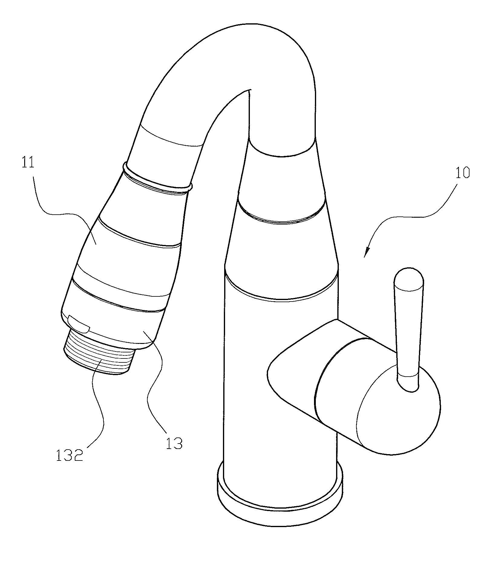
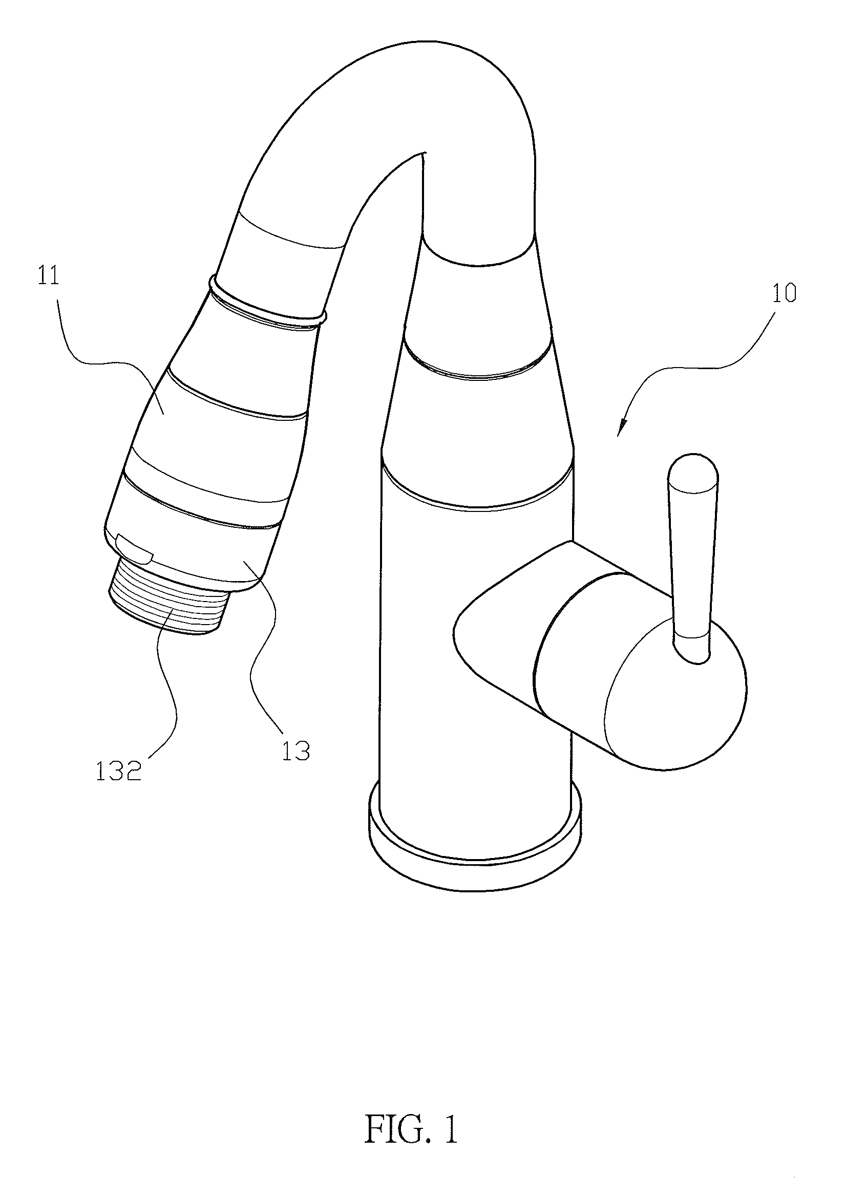
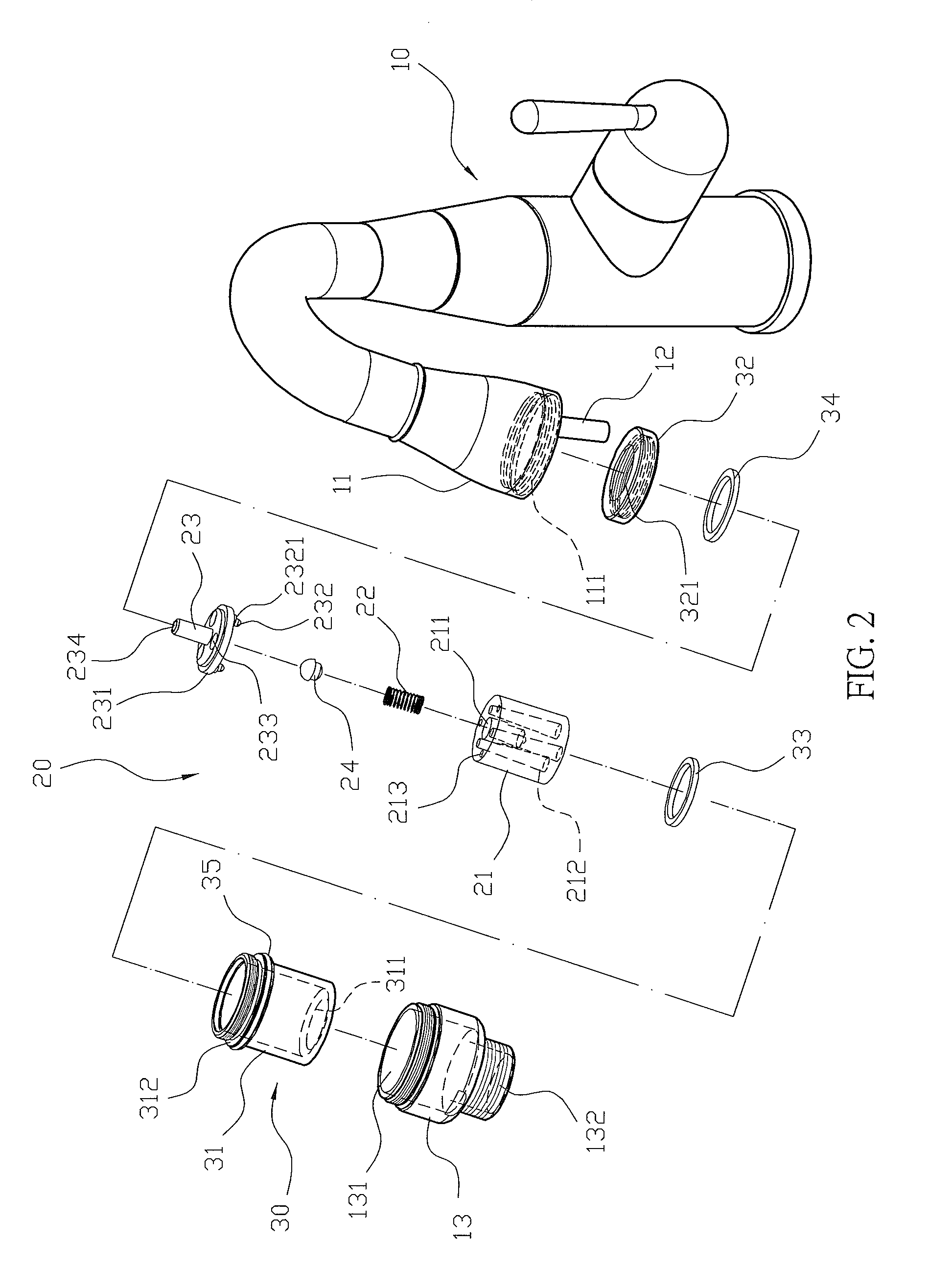
[0025]With reference to FIGS. 1-3, an ozone faucet according to a preferred embodiment of the present invention comprises a body 10, a mixer 20, and a fixing member 30.

[0026]The body 10 includes an outlet end 11, an ozone tube 12 disposed on the outlet end 11, and the outlet end 11 has inner threads 111 defined around an inner wall thereof and screwing with a casing 13, and between the casing 13 and the outlet end 11 is defined an accommodating space 131, the casing 13 has a screwing section 132 formed around a lower end thereof so as to screw with a spray component 14 (as shown in FIG. 6), and the spray component 14 is a shower head.

[0027]The mixer 20 includes a water guiding member 21, a resilient element 22, and a check tube 23. The water guiding member 21 has a recess 211 defined on a central portion thereof and a plurality of increasingly conical orifices 212 surrounding around the recess 211, and a wide end of each increasingly conical orifice 212 faces to a lower end of the c...


PUM

PropertyMeasurementUnit
pressureaaaaaaaaaa
diameteraaaaaaaaaa
resilientaaaaaaaaaa

Abstract

An ozone faucet contains a body and a mixer. The body includes an outlet end and an ozone tube, and the outlet end has inner threads for screwing with a casing, between the casing and the outlet end is defined an accommodating space. The mixer includes a water guiding member, a resilient element, and a check tube. The water guiding member has a groove and a plurality of increasingly conical orifices, the resilient element is accommodated in the groove and has a stopping plug pushed by the resilient element. The check tube has a disc covering the water guiding member, the disc has a plurality of decreasingly conical apertures matching with the plurality of increasingly conical orifices The check tube also has a channel passing therethrough and contacting with the stopping plug, the mixer is secured in the accommodating space, and the check tube connects with the ozone tube.

Description

FIELD OF THE INVENTION[0001]The present invention relates to a faucet structure, and more particularly to an ozone faucet which is assembled easily and mixes water and ozone together.BACKGROUND OF THE INVENTION[0002]Conventional ozone supply member is coupled with an outlet end of a faucet so as to supply water with ozone. With reference to FIG. 7, a conventional ozone faucet contains an outlet end 40, and the outlet end 40 has an ozone tube 41 extending outwardly therefrom. The outlet end 40 has a check valve 50, a control ring 42, an aerator 43, and a spray head 44. The check valve 50 has a first end disposed on the ozone tube 41 and has a second end with a joining section 51. The check valve 50 further has a guiding hole 52 passing therethrough, a valve tube 53 inserted into the guiding hole 52, a stopping fringe 54 defined on a first end of the valve tube 53, and a closing ring 55 fitted on a second end of the valve tube 53. The control ring 42 has an air inlet 421 defined on a ...

Claims


Application Information

Patent Timeline
Patent Type & Authority Patents(United States)
IPC IPC(8): C02F1/78B05B1/00B01F3/04C02F1/68E03C1/04E03C1/046
CPCC02F1/78B01F3/04099B05B1/00C02F1/685E03C1/046B01F2003/04886C02F2201/784C02F2307/06E03C2201/40B01F23/23B01F23/237613
Inventor WANG, HSIANG-SHIH
Owner GEANN IND
Why Eureka
Try Eureka