Communications network

a communication network and optical signal technology, applied in the field of optical communication networks, can solve the problems of increasing the cost and complexity of the network, the optical signal required to transmit such data rates may not fit into the wavelength grid defined in the dwdm specifications, and the difficulty of recovering the transmitted signal at the receiver, so as to achieve the effect of increasing the information carrying capacity of the fiber and increasing customer demand

Active Publication Date: 2016-02-23
BRITISH TELECOMM PLC
View PDF22 Cites 11 Cited by
  • Summary
  • Abstract
  • Description
  • Claims
  • Application Information

AI Technical Summary

Benefits of technology

[0010]Such an optical network enables different, and potentially incompatible, optical signals to be transmitted within the same optical fiber. This may enable network operators to ^ expand and upgrade their networks in a more flexible manner. For example, a portion of the transmission window could be used to deploy immediately a number of conventional wavelengths using DWDM and reserve a portion of the transmission window for coherent or flexgrid optical signals. In the medium to long term, these more advanced transmission technologies can be deployed in the second wavelength region. Over time, the size of the second wavelength region can be increased relative to the first wavelength region such that the information carrying capacity of the fiber can be increased by replacing 1 QGb / s DWDM signals with 40 Gb / s coherent signals or 100 Gb / s flexgrid signals. Embodiments flexible deployment path which enables a network operator to invest in new transmission capacity as technologies improve and customer demand increases. Without embodiments disclosed herein, a network operator has to install a network with a single type of transmission technology and hope that their forecasts are correct.

Problems solved by technology

One of the transmission phenomena present in optical fibers is chromatic dispersion, which causes the transmitted pulse to spread out, such that it becomes difficult to recover the transmitted signal at the receiver.
The effects of dispersion can be mitigated by installing dispersion compensating modules (DCMs) into the network, but this adds to the cost and the complexity of the network.
As data transmission rates increase further, for example beyond 100 Gb / s, then the optical signals required to transmit such data rates may not fit into the grid of wavelengths that are defined in the DWDM specifications.

Method used


Image

  • Communications network
  • Communications network
  • Communications network

Examples


Embodiment Construction

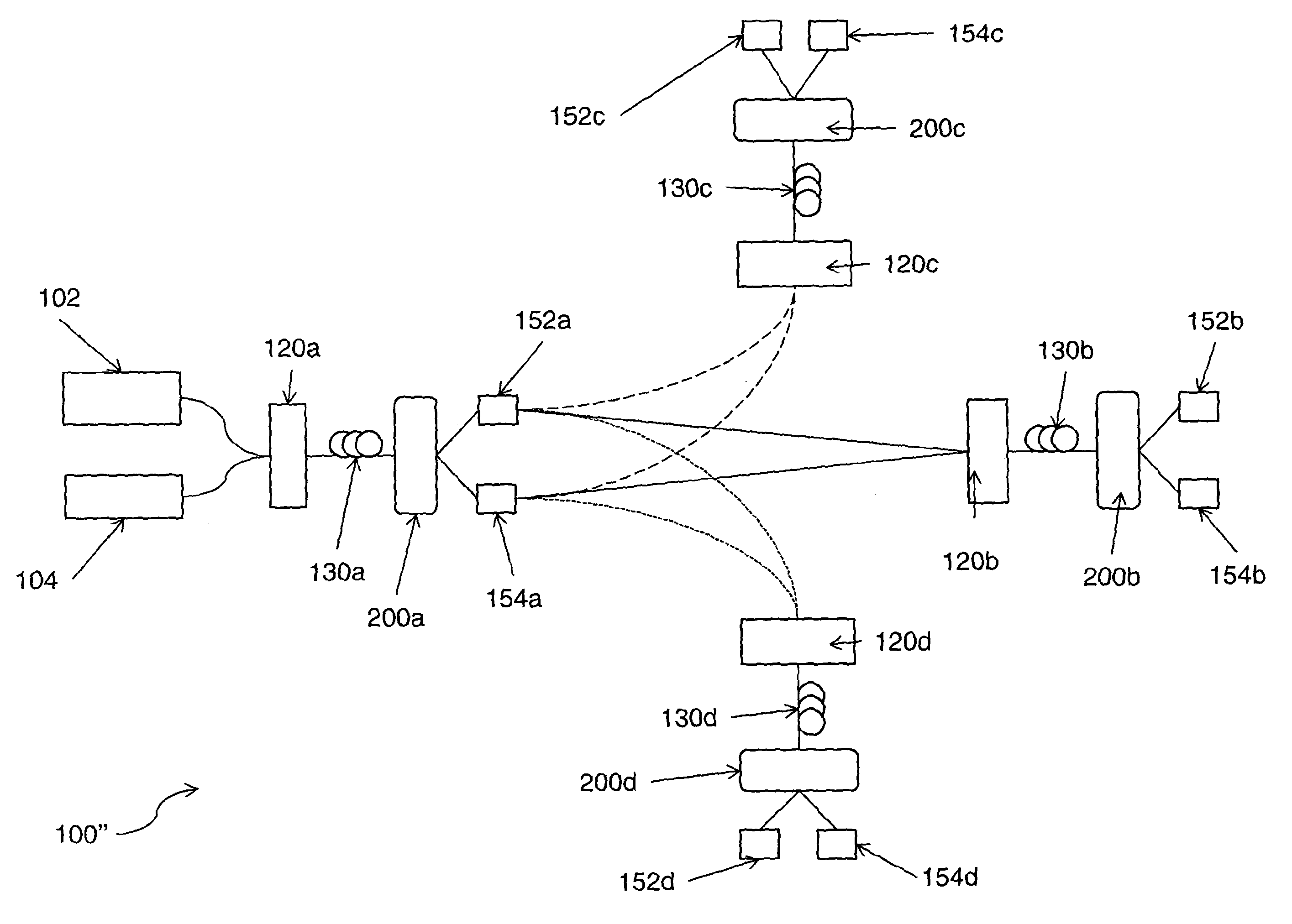
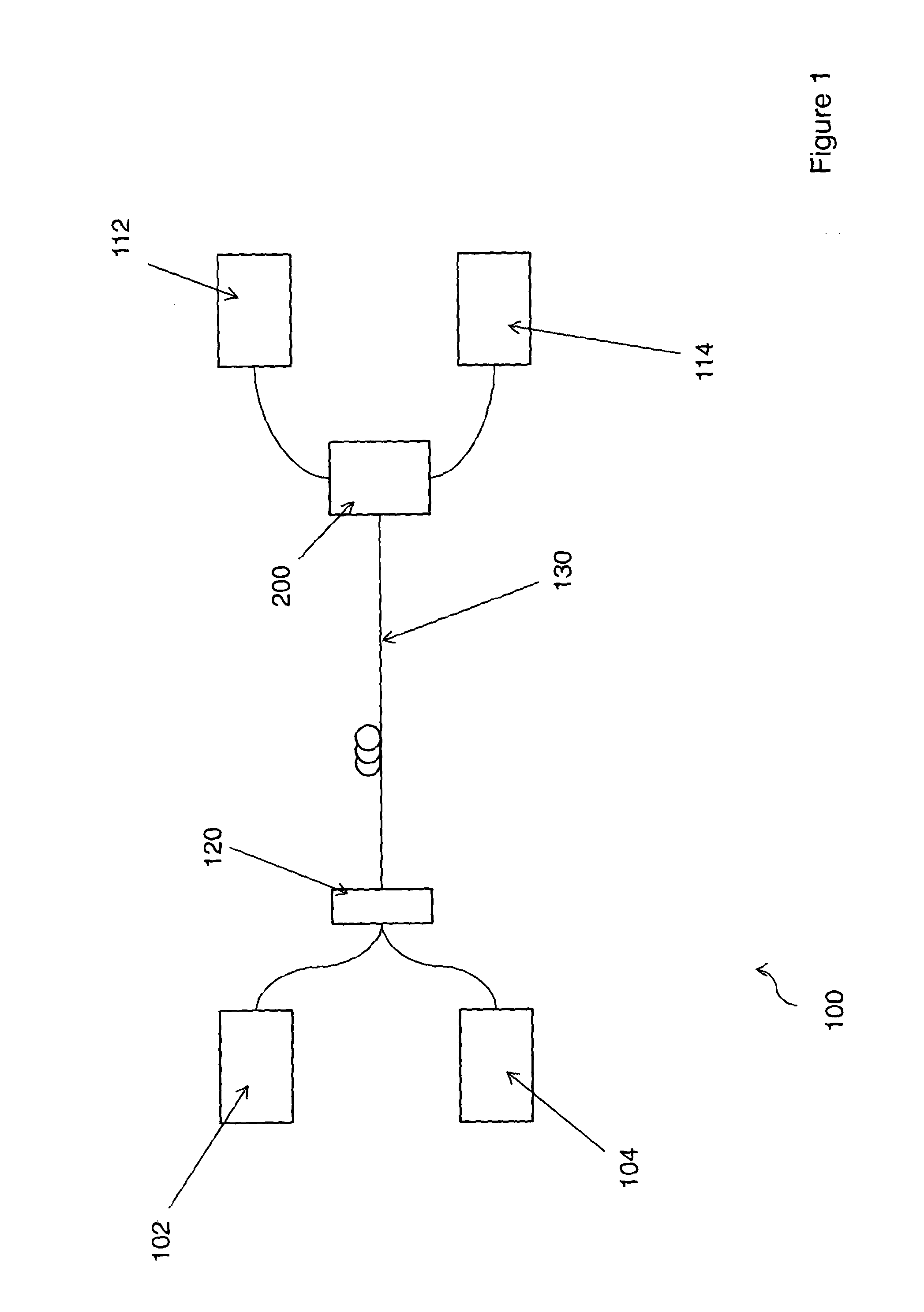
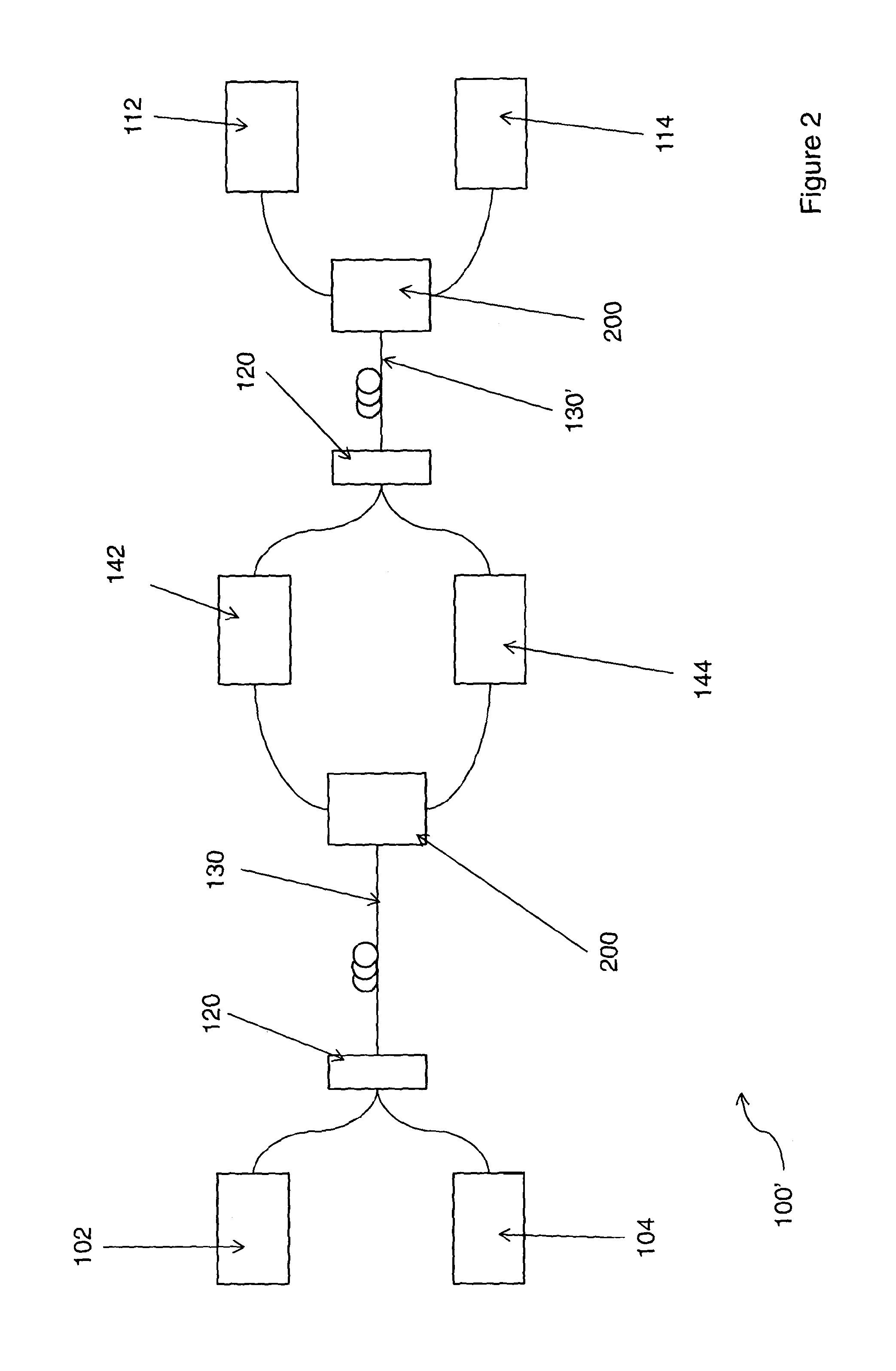
[0020]FIG. 1 shows a schematic depiction of a communications network 100 according to a first aspect of the present invention. The network comprises a single span of optical fiber 130 which connects a first location to a second location. At the first location a first optical transmitter 102 is connected to the optical fiber 130 via an optical coupler 120. There is also provided at the first location a second optical transmitter 104 which is also coupled to the optical fiber 130 via the optical coupler 120. At the second location a tunable splitter 200 connects the second end of the optical fiber 130 to first optical receiver 112 and second optical receiver 114.

[0021]The first optical transmitter operates in a first region of a fiber transmission window and the second optical transmitter operates in a second region of that fiber transmission window. For example, the first optical transmitter may generate a first set of optical signals between 1525 and 1543 nm and the second optical t...


PUM


Abstract

A communications network wherein first and second optical signals can be launched into an optical fiber in respective first and second regions of a transmission window such that controllable filters can be used to selectively recover the first and second optical signals. This partitioning of the transmission window allows two incompatible optical signals to coexist in the same optical fiber.

Description

PRIORITY CLAIM[0001]The present application is a National Phase entry of PCT Application No. PCT / GB2012 / 000528, filed Jun. 18, 2012, which claims priority from EP Patent Application No. 11250602.7, filed Jun. 20, 2011, and GB Patent Application No. 1112713.1, filed Jul. 25, 2011, said applications being hereby incorporated by reference herein in their entireties.TECHNICAL FIELD[0002]The present application relates to an optical communications network and in particular to an optical communications network which can support optical signals of different formats.BACKGROUND[0003]Conventional optical communication networks operate by sending light pulses of a predetermined period, for example such that a pulse represents a ‘1’ and no pulse represents a ‘0’. This technique enables signals to be sent at data rates of up to 10 Gb / s and wavelength division multiplexing (WDM) techniques can be used to send multiple signals over a single fiber. Dense WDM (DWDM) enables up to 160 wavelengths to ...

Claims


Application Information

Patent Timeline
Patent Type & Authority Patents(United States)
IPC IPC(8): H04J14/00H04J9/00H04Q11/00H04J14/02
CPCH04Q11/0005H04J9/00H04J14/02
Inventor LORD, ANDREW
Owner BRITISH TELECOMM PLC
Why Eureka
Try Eureka