Improvements to multi-hull vessel suspension geometry

a multi-hull, suspension technology, applied in the field of watercraft, can solve the problems of increasing the friction of sliding joints, reducing the life and ride comfort of joints, and more bending induced into the body and/or hull

Active Publication Date: 2016-03-01
NAUTI CRAFT PTY LTD
View PDF4 Cites 5 Cited by
  • Summary
  • Abstract
  • Description
  • Claims
  • Application Information

AI Technical Summary

Benefits of technology

[0006]The at least one sliding axis of the first locating linkage may include at least two laterally spaced sliding axes defining a first sliding plane and the line of action of the support force of the first support element may be substantially aligned with said first sliding plane. The line of action of the support force of the first support element may be substantially aligned with both the first linkage plane (and the first sliding plane) to thereby minimise bending moments and side loads in the first locating linkage resulting from the support force.
[0011]Alternatively, the at least one sliding axis may be a pair of parallel first and second laterally spaced sliding axes. Bearings or bushings may be provided between the first part and the second part and may be arranged to effectively constrain the relative motion between the first and second parts to a linear sliding motion along said first and second laterally spaced sliding axes, said sliding axes being parallel to each other and substantially perpendicular to the body and hull end pivot axes.
[0025]The first sliding axis may be within 40 degrees of vertical relative to the main body during operation. From a force standpoint, ideally the first sliding axis is substantial vertical with respect to the main body to minimise the longitudinal component of the support force input from the first locating linkage into the main body. However the geometry of the second locating linkage can require the first sliding axis to deviate from vertical. Also from a packaging standpoint it can be preferable to angle the first sliding axis from vertical to reduce the requirement for the first locating linkage to penetrate the hull or a deck area of the vessel.

Problems solved by technology

The support forces are provided by rams which provide a moment on the trailing arms which can require the trailing arms to be of very high strength and large section on some vessels and places a high side load on the sliding joints of the variable length arm which increases the friction of the sliding joints and therefore reduces joint life and ride comfort.
Alternatively the rams are provided connected directly between the body and the hull, which can require a large tower on the deck of the body to accommodate the rams which can be difficult to package in some vessel designs and layouts.
Also wherever the suspension arms and rams are located in separate areas of the vessel, having separate load paths through respective mounting points into the body and / or the hull(s), the greater the spacing between the respective mounting points, generally the more bending induced into the body and / or hull and the less efficient the design in terms of packaging and weight.

Method used


Image

  • Improvements to multi-hull vessel suspension geometry
  • Improvements to multi-hull vessel suspension geometry
  • Improvements to multi-hull vessel suspension geometry

Examples


Embodiment Construction

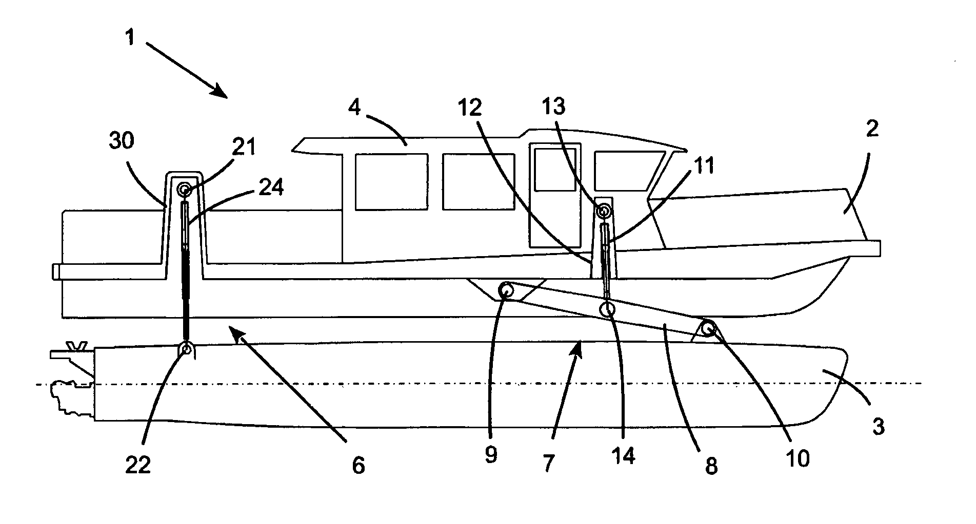
[0042]Referring initially to FIG. 1 there is shown a catamaran 1 with a main body 2 suspended above the independently moveable hulls 3. The gunnels on the near side are omitted to fully expose the cabin 4 and the hull locating arrangement for the visible hull. The hull locating arrangement comprises a back hull locating linkage 6 and a front hull locating linkage 7.

[0043]The front locating linkage shown includes a leading arm 8 rotatably connected to the body 2 by pivot 9 such as bearings or bushings and rotatably connected to the hull 3 by pivot 10. This provides lateral, longitudinal and roll constraints to the motion of the hull relative to the body. Although it can also provide a yaw constraint, the use of a second lateral constraint at a longitudinally spaced position (i.e. the back locating linkage) generally provides most of the yaw reaction. A front support means 11 (such as a spring damper unit or one or more hydraulic cylinders) is provided, packaged inside a suspension to...


PUM


Abstract

A hull locating arrangement for a multi-hulled vessel having a body at least partially suspended above at least a first and a second hull by support components is disclosed. The hull locating arrangement comprises, for a hull, a first locating linkage and a second locating linkage to together constrain the hull in the lateral, longitudinal, roll and yaw directions relative to the body. The first and second locating linkages are longitudinally spaced, and the first locating linkage includes a first part and a second part, one of the parts of the first locating linkage being pivotally connected to the body about a body end pivot axis, and the other of the parts being pivotally connected to the hull about a hull end pivot axis. The first locating linkage is also arranged to permit relative motion between the first and second parts along at least one sliding axis to thereby permit the first locating linkage to vary in length between the body end pivot axis and the hull end pivot axis. The support components include a first support component adjacent the first locating linkage, the first support component including a first support element providing a support force supporting a portion of the body above the first hull. The support force of the first support element has a line of action that is within thirty degrees of parallel to a first linkage plane extending through the body end pivot axis and the hull end pivot axis.

Description

FIELD OF THE INVENTION[0001]The present invention is generally directed to water craft and in particular to methods of or systems / arrangements for at least partially suspending or supporting a body above at least two movable hulls.BACKGROUND OF THE INVENTION[0002]In the applicant's earlier International Patent Application Numbers PCT / AU2011 / 000557 and PCT / AU2011 / 000565 there are disclosed various configurations of catamaran, trimaran and quadmaran all having resilient suspension between at least two laterally spaced hulls and central hull or body. Where two longitudinally spaced locating linkages are provided between one hull and the body some form of longitudinal compliance or freedom is required in one of the locating linkages. For example to locate one hull relative to the body, a front fixed length trailing arm is used and a back variable length trailing arm is used. The variable length of the back trailing arm is provided by telescopic or sliding sections in the arm or by a dro...

Claims


Application Information

Patent Timeline
Patent Type & Authority Patents(United States)
IPC IPC(8): B63B1/12B63B17/00B63B39/00B63B1/14
CPCB63B1/121B63B1/14B63B17/00B63B39/00B63B2001/123B63B2017/0072B63B27/14B63B27/30B63B39/04B63B2001/145
Inventor HEYRING, CHRISTOPHER, BRIANCATONI, JOHN, GERARDSAMPSON, MARK, DAVID
Owner NAUTI CRAFT PTY LTD
Why Eureka
Try Eureka