
Laser-guided projectile system

a projectile and laserguide technology, applied in the direction of direction controllers, cartridge ammunition, weapons, etc., can solve the problems of significant alteration of the flight trajectory of the projectile, projectile also experiences deceleration due, and difficulty in compensating

Active Publication Date: 2016-03-08
GOLDBERG MARSHALL PHILLIP
View PDF24 Cites 4 Cited by
  • Summary
  • Abstract
  • Description
  • Claims
  • Application Information

AI Technical Summary

Benefits of technology

The present invention is a laser-guided projectile system that can adjust the flight trajectory of a projectile by correcting external and internal ballistic factors that affect the flight trajectory. This system is designed to improve the accuracy and safety of projectiles fired from a firearm. The invention uses a laser to guide the projectile to its target, making the shot more reliable and reducing the risk of collateral damage or danger to the shooter. The invention is affordable, easy to implement, and can be used with existing firearms and projectiles. The system includes a housing sleeve, a laser tunnel generator assembly, and a calibration laser. The invention also includes a plurality of laser-combustible microcapsules that are enclosed within or externally layered onto the projectile. The invention can be used in various applications such as hunting, target practice, and self-defense.

Problems solved by technology

The projectile also experiences deceleration due to drag while traveling to the target.
Crosswinds can also significantly alter the flight trajectory of the projectile, particularly over large distances.
Many of the external ballistics of a projectile are variable environmental factors and are difficult to compensate for.
The importance of a properly aimed shot is paramount as poorly aimed shots can result in collateral damage or danger to the shooter from enemy / adversary return fire.
Current technology introduces projectiles that feature complex internal propulsion, guidance, and control systems.
However, this technology is expensive as well as difficult to implement.
In addition, because these propulsion, guidance, and control systems are integrated into the projectile itself, the technology cannot be utilized with existing firearms and projectiles.

Method used


Image

  • Laser-guided projectile system
  • Laser-guided projectile system
  • Laser-guided projectile system

Examples


Embodiment Construction

[0020]All illustrations of the drawings are for the purpose of describing selected versions of the present invention and are not intended to limit the scope of the present invention.

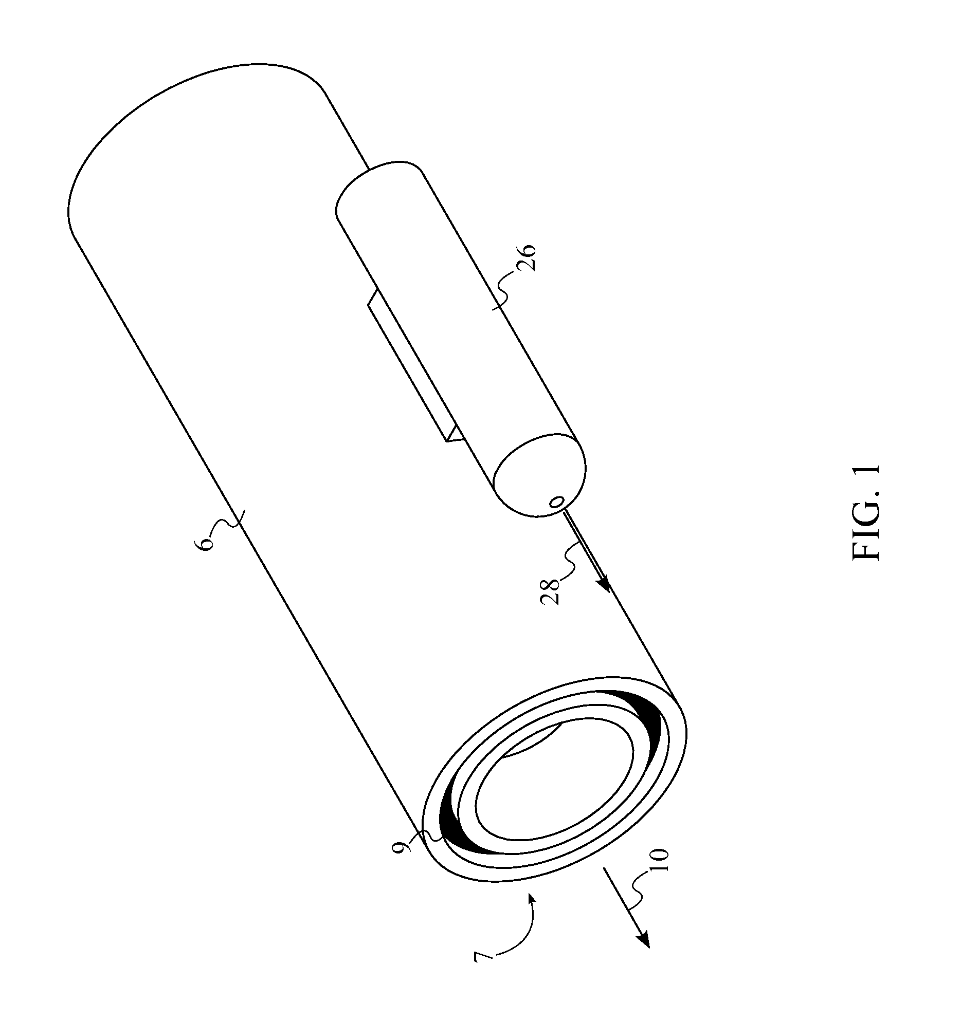
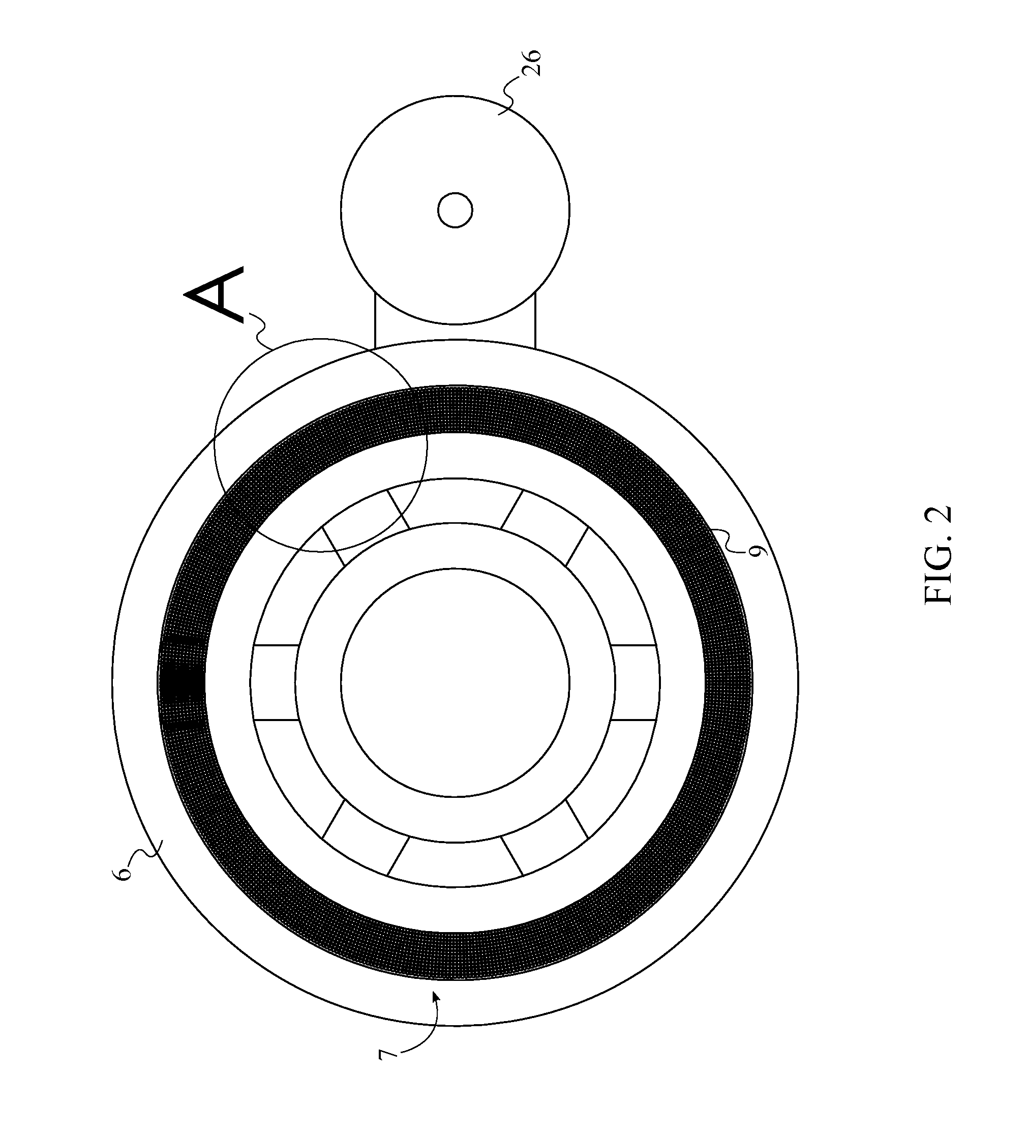
[0021]The present invention is a laser-guided projectile system that is able to adjust the flight trajectory of a projectile by correcting the external and internal ballistic factors that affect the flight trajectory of the projectile. The present invention is shown in FIGS. 1-7 and comprises a firearm 1, a housing sleeve 6, a laser tunnel generator assembly 7, a cartridge 11, and a trajectory-correcting actuator 15. The cartridge 11 comprises a projectile 12 that is discharged from the firearm 1. The firearm 1 is preferably a long-barrel firearm such as a rifle to provide sufficient space for the housing sleeve 6. The firearm 1 is additionally preferably equipped with a scope that is capable of detecting both infrared light and visible light. The housing sleeve 6 contains and protects the components of ...


PUM


Abstract

A laser-guided projectile system is a system for correcting the external and internal ballistic factors that affect the flight trajectory of a projectile that is traveling to a target. A laser tunnel generator assembly and a housing sleeve are mounted to a barrel of a firearm. A laser tunnel is projected forward from the firearm and the projectile is able to travel within the laser tunnel. When the projectile comes into contact with the laser tunnel due to ballistic factors, a plurality of explosive outputs is generated and the projectile is directed back toward the center of the laser tunnel. The plurality of explosive outputs is evenly distributed about an aerodynamic portion of the projectile to allow the plurality of explosive outputs to correct the flight trajectory, regardless of the portion of the projectile that comes into contact with the laser tunnel.

Description

[0001]The current application claims a priority to the U.S. Provisional Patent application Ser. No. 62 / 047,890 filed on Sep. 9, 2014.FIELD OF THE INVENTION[0002]The present invention relates generally to a system for guiding a projectile to a target. More specifically, the present invention is a laser-guided projectile system that adjusts the flight trajectory of a discharged projectile by correcting all external and internal ballistic factors that affect the flight trajectory of the projectile.BACKGROUND OF THE INVENTION[0003]The flight trajectory of a projectile that has been discharged from a firearm is affected by a large number of factors. Gravity causes the projectile to descend while traveling to a target in an effect known as bullet drop. The projectile also experiences deceleration due to drag while traveling to the target. Crosswinds can also significantly alter the flight trajectory of the projectile, particularly over large distances. Ambient air density is an additional...

Claims


Application Information

Patent Timeline
Patent Type & Authority Patents(United States)
IPC IPC(8): F42B10/60F42B10/66F42B30/02F42B5/02F41G7/24F42B15/01F41G7/26
CPCF42B15/01F42B30/02F42B10/60F42B10/66F41G7/24F41G7/266F41G7/263F42B5/02
Inventor GOLDBERG, MARSHALL, PHILLIP
Owner GOLDBERG MARSHALL PHILLIP
Learn More