
Apparatus and method for receiving a touch input

a touch input and touch technology, applied in the field of touch screens, can solve the problems of resistive devices that can also be sensitive to humidity, require excessive power usage, and dim the underlying screen, and achieve the effect of reducing the cost of both the bill of materials and product assembly

Inactive Publication Date: 2016-03-08
ZETTA RES & DEV LLC RPO SERIES
View PDF7 Cites 25 Cited by
  • Summary
  • Abstract
  • Description
  • Claims
  • Application Information

AI Technical Summary

Benefits of technology

The present invention aims to improve infrared-style touch screens by reducing the bezel width on at least two sides of the input area. Additionally, the invention aims to provide screens that require fewer components, reducing costs in both the bill of materials and product assembly and manufacturing.

Problems solved by technology

The most common approach uses a flexible resistive overlay, although the overlay is easily damaged, can cause glare problems, and tends to dim the underlying screen, requiring excess power usage to compensate for such dimming.
Resistive devices can also be sensitive to humidity, and the cost of the resistive overlay scales quadratically with perimeter.
In this case the overlay is generally more durable, but the glare and dimming problems remain.
It will be appreciated that the associated ‘bezel width’ on all four sides limits the available display size within a given consumer electronics device, which may be a significant limitation for small devices such as mobile phones.
Excessive bezel width can also be a problem for incorporating the additional functionality of infrared touch within an existing device design.
Furthermore it will be appreciated that there is a component-related cost associated with having components on all sides of the display as well as extra assembly and manufacturing costs.

Method used


Image

  • Apparatus and method for receiving a touch input
  • Apparatus and method for receiving a touch input
  • Apparatus and method for receiving a touch input

Examples


Embodiment Construction

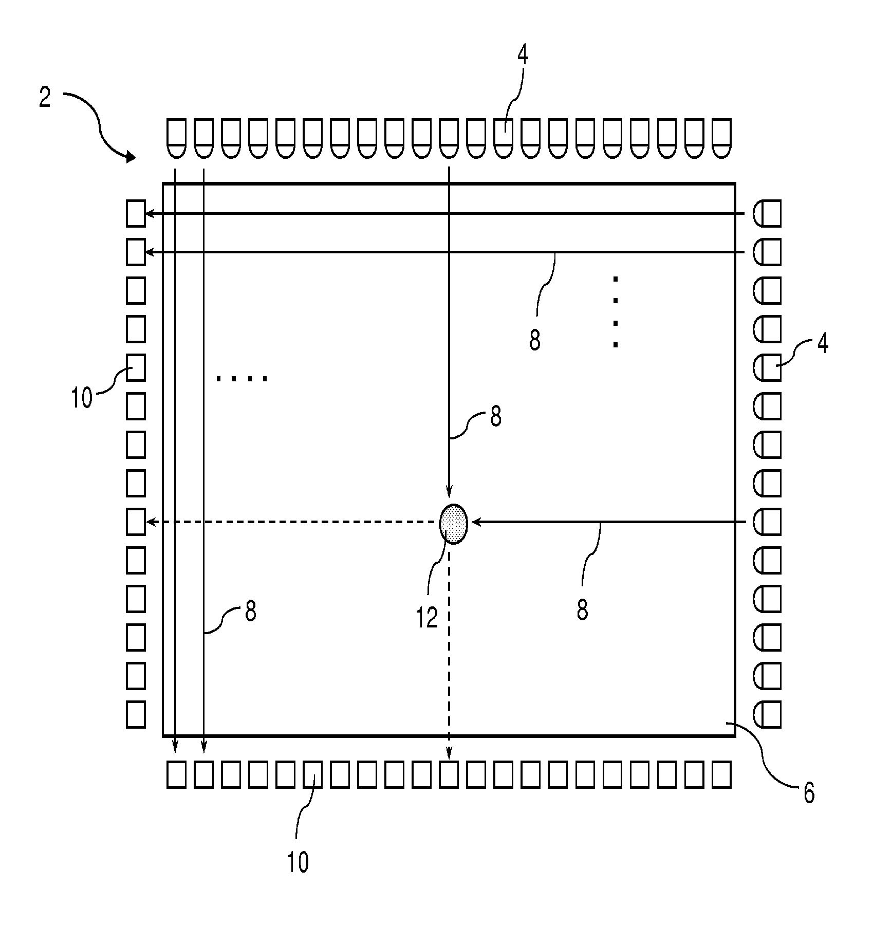
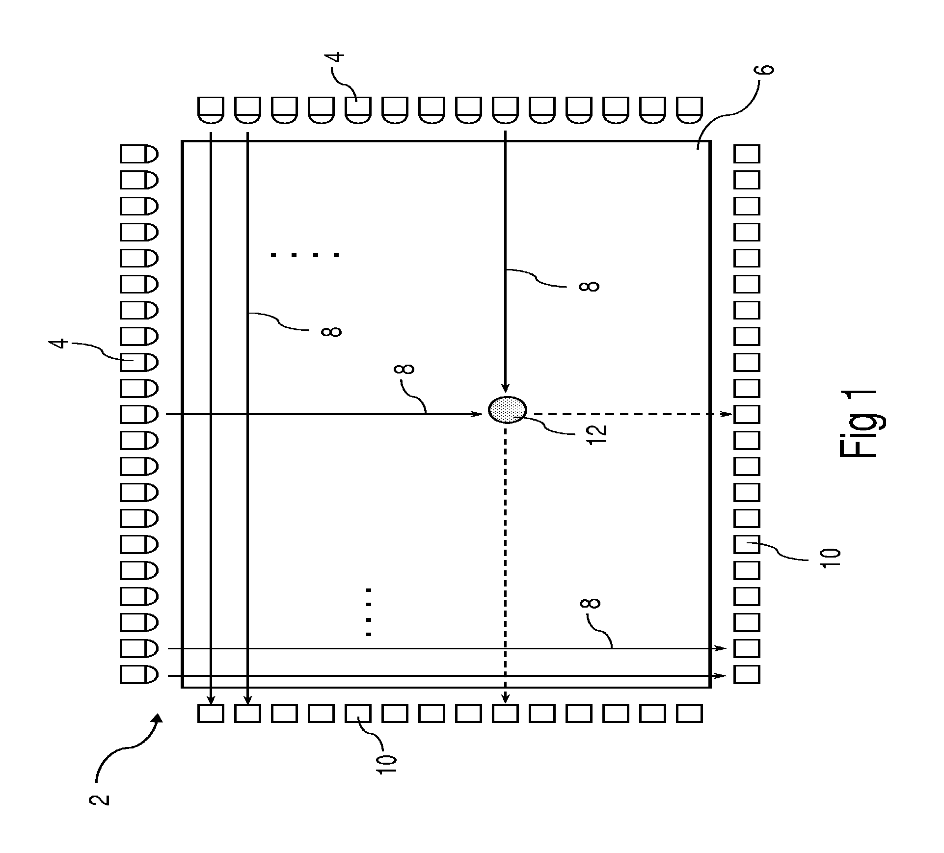
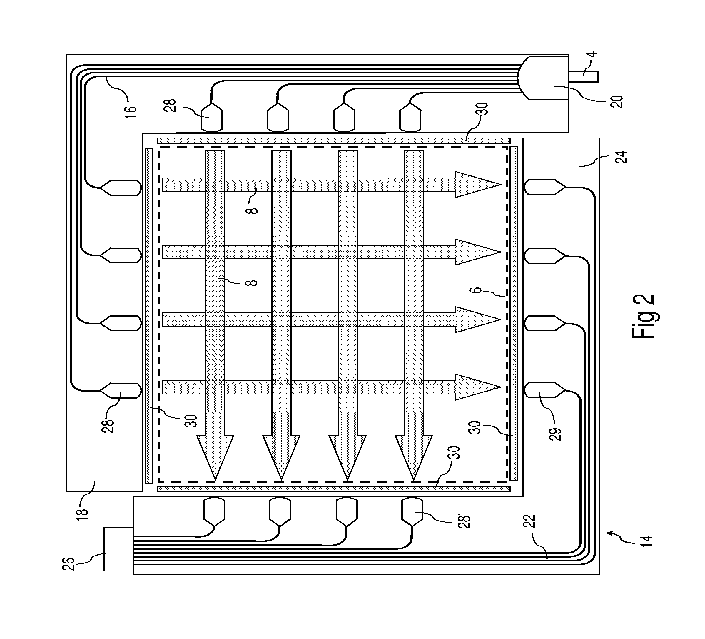
[0101]FIG. 4 shows in plan view a schematic of a mobile phone 44 equipped with a touch screen 46, an on / off switch 48 and a speaker 50. A particular feature of the touch screen shown here is that it has minimal bezel width on two opposing sides 52, 52′, enabling it to occupy essentially the full width of the mobile phone, increasing the available screen area and possibly resulting in a more aesthetically pleasing appearance. The need for small bezel width along the other two sides is clearly less pressing. In this section some variations of the ‘discrete component’, ‘waveguide-based’ and ‘light guide plate’ styles of infrared touch screen (as shown in FIGS. 1, 2 and 3 respectively) are described that have the desired minimal bezel width on two opposing sides.

[0102]FIGS. 5A and 5B show plan and side views of a ‘light guide plate’ infrared touch screen 54 according to one embodiment of the present invention, comprising: an emitting system in the form of a ‘single axis’ transmissive bo...


PUM


Abstract

Infrared-style touch screens are described having light emission means and light detection means along only two opposing sides of a touch input area, which are nevertheless able to detect and locate a touch object in two dimensions. Certain embodiments use an edge-blurring algorithm to determine the second coordinate, while other embodiments use a form of stereo-scopic vision to determine both coordinates by triangulation. These touch screens have minimal bezel width along two opposing sides of the touch input area, and also offer cost reductions associated with components and product assembly and manufacturing.

Description

RELATED APPLICATIONS[0001]The present application claims priority from Australian provisional patent application Nos. 2009905626 and 2010902780, and from U.S. provisional patent application No. 61 / 347,330, the contents of which are incorporated herein by reference.FIELD OF THE INVENTION[0002]The present invention relates to touch screens, and in particular to infrared-style touch screens having relatively fewer components, reduced bezel dimensions and / or lower cost. However, it will be appreciated that the invention is not limited to this particular field of use.BACKGROUND OF THE INVENTION[0003]The following discussion of the prior art is provided to place the invention in an appropriate technical context and enable the advantages of it to be more fully understood. It should be appreciated, however, that any discussion of the prior art throughout the specification should not be considered as an express or implied admission that such prior art is widely known or forms part of common ...

Claims


Application Information

Patent Timeline
Patent Type & Authority Patents(United States)
IPC IPC(8): F21V8/00G06F3/042
CPCG06F3/0421G06F3/0428G02B6/0028G02B27/30G06F3/042
Inventor KUKULJ, DAX
Owner ZETTA RES & DEV LLC RPO SERIES
Learn More