Adjustable screen tensioning system

a tensioning system and adjustable technology, applied in the field of windows and doors, can solve the problems of affecting the strength and appearance of the screen attached using simple fasteners, unable to apply tension upon installation, and inability to meet the requirements of installation, so as to prevent galvanic corrosion and increase the resistance to screen impact loading

Active Publication Date: 2016-03-15
C R LAURENCE
View PDF46 Cites 9 Cited by
  • Summary
  • Abstract
  • Description
  • Claims
  • Application Information

AI Technical Summary

Benefits of technology

[0011]It is the purpose of the present invention to provide an improved channel-based screen retention system that increases the resistance to screen impact loading; provides for a broad range of screen tensioning adjustability, and that electrically isolates the screen from the walls of the channel to prevent galvanic corrosion, among other features.
[0013]The inner perimeter of the members which form the frame for the screen include an opening or main channel for receipt of the screen. In cross section, an upper interior wall of the main channel of each frame member has a serrated surface while an opposing lower, interior wall features a pair of spaced apart inner and outer interior longitudinal channels. The interior longitudinal channels serve to secure an elastomeric gasket. A substantial depth of clear space exists inwardly of the serrations and a bottom of the main channel. The depth of free space allows for a broad range of adjustability for tensioning the screen.

Problems solved by technology

While such systems are functional, they lack a means of applying tension to the screen upon installation.
Thus, the semi-rigid material of the screen often appears floppy after a short period of ordinary use.
The strength and appearance of a screen attached using simple fasteners is also overly dependent on the skill of the fabricator.
For example, if the screen is cut slightly too small, the screen will be weakened and subject to pulling out of the frame because the fasteners will be too close to the edge of the mesh.
If glue is used, it will not sufficiently cover enough surface area of the mesh to create a strong bond.
On the other hand, if the screen is cut slightly to large, then the mesh will be unavoidably floppy because the use of simple fasteners provide no means for tensioning the mesh.
Prior an channel-based screen retention systems do suffer from certain drawbacks however.
In particular, prior art systems typically use flat or screen edges which allow for only a very limited amount of screen tensioning and offer only modest resistance to screen impact loading.
When screen tensioning provisions are specifically provided, they nevertheless often have a very limited adjustment range.

Method used


Image

  • Adjustable screen tensioning system
  • Adjustable screen tensioning system
  • Adjustable screen tensioning system

Examples


Embodiment Construction

[0023]The present invention will now be described more fully hereinafter with reference to the accompanying drawings, in which preferred embodiments of the invention are shown. The invention may, however, may be embodied in many different forms and should not be construed as being limited to the embodiments set forth herein. Rather these embodiments are provided so that this disclosure will be thorough and complete, and will fully convey the scope of the invention to those skilled in the art. Like numbers refer to like elements throughout.

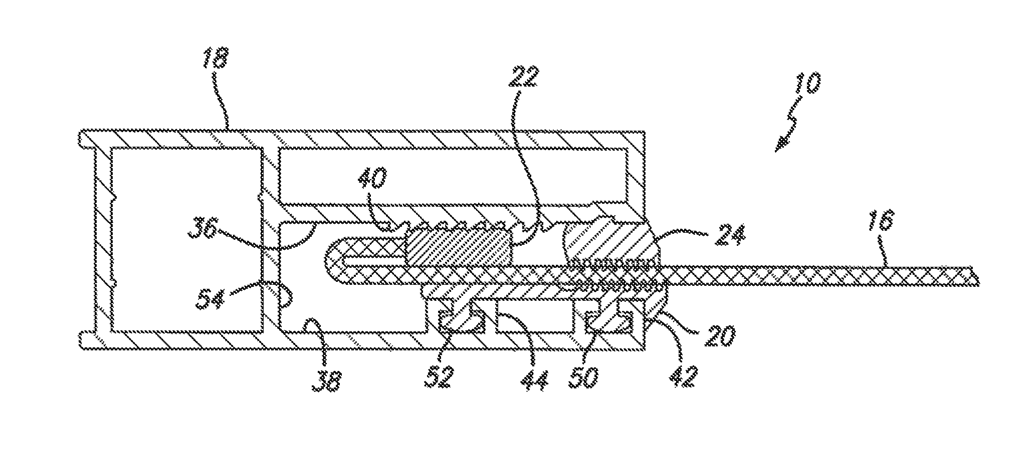
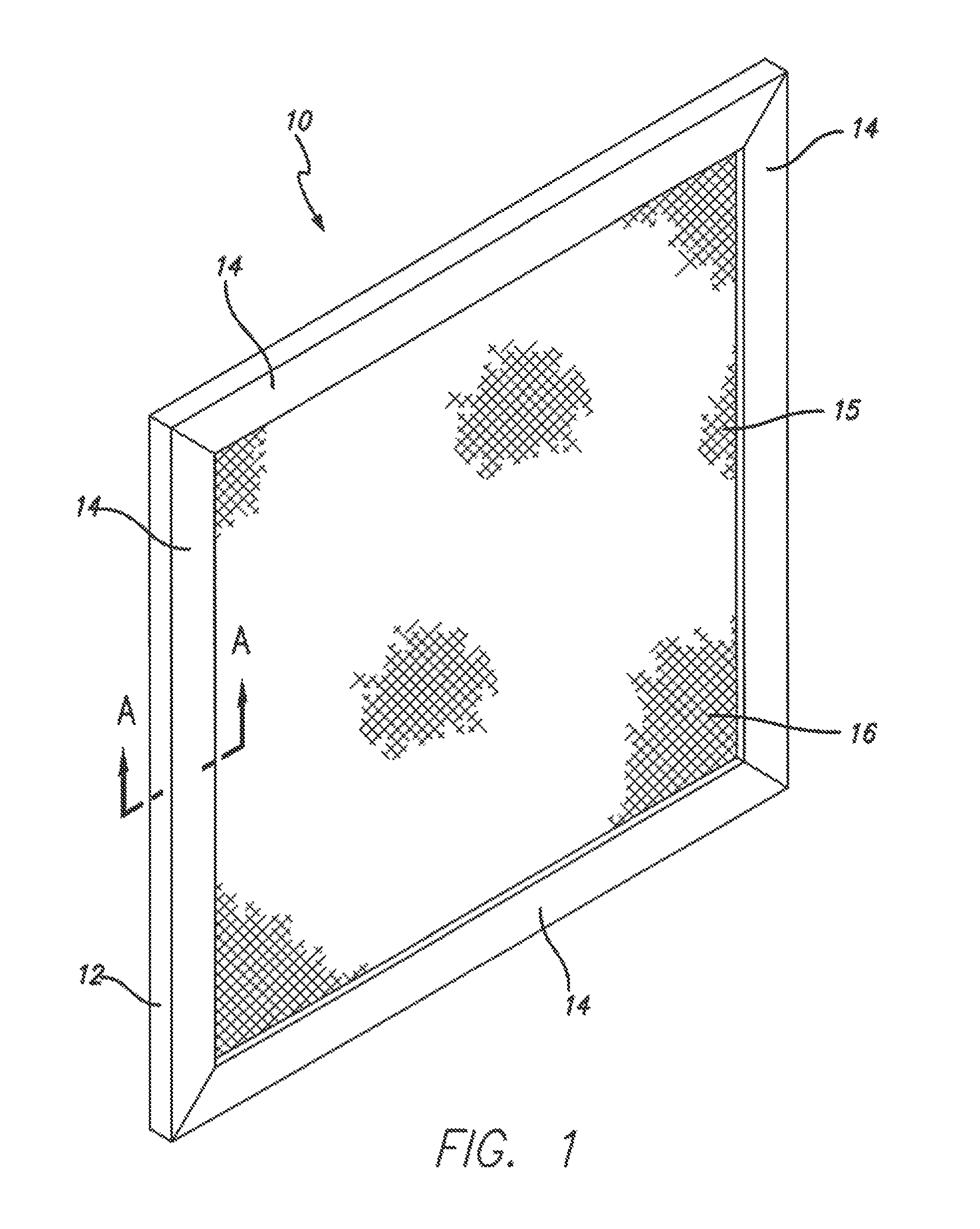
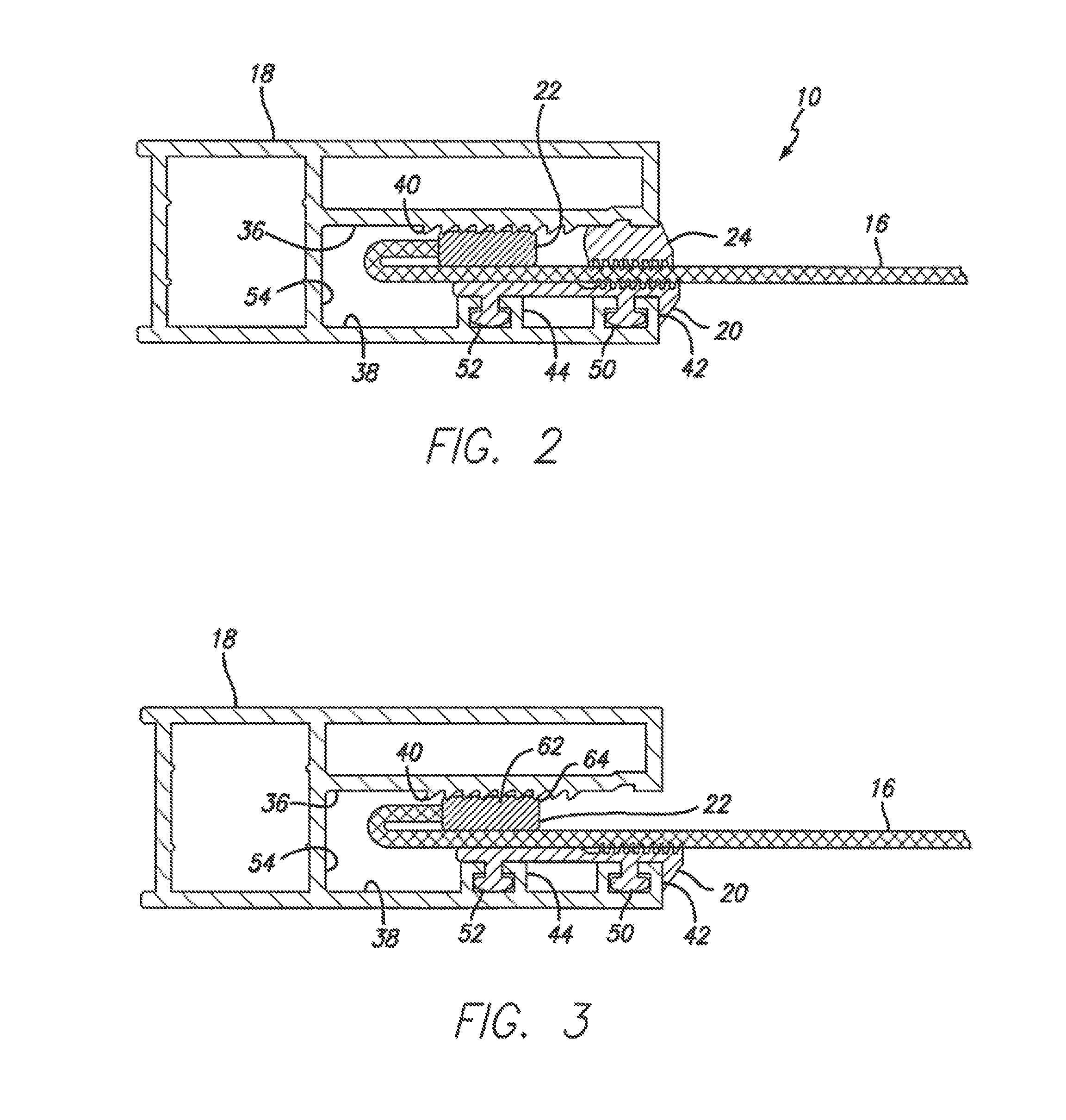
[0024]With reference to FIG. 1, there is illustrated a screen retention system 10 having a frame 12 comprised of elongate frame members 14 having channel cross sections 18 with a mesh or perforate screen 16, attached to the frame members 14. The screen 16 covers the opening enclosed by the frame 12. In the exemplary embodiment of FIG. 1, the screen retention system 10 is shown as having a discrete frame 12, the outside perimeter of which is sized t...


PUM


Abstract

An adjustable screen re don system is presented. The present invention screen retention system comprises a mesh Of perforate screen retained within a frame composed of frame members have channel cross sections. The screen is formed with a rolled or U-shaped edge hem. The edge hem having a free edge that folds inwardly over the inner face of the screen and is parallel to, and spaced above, the inner face of the screen. The framing members are channel section extrusions which contain features for retaining, tensioning and locking the screen. The adjustable screen retention system herein presented improves upon the prior art by providing a more secure attachment of the screen within the channel of the frame members thereby providing increased resistance to screen impact loading. The new system also provides for a broader range of screen of tensioning adjustment than has heretofore been available and further electrically isolates the screen from the walls of the channel.

Description

BACKGROUND OF THE INVENTION[0001]1. Field of the Invention[0002]The present invention relates to screens for windows, doors and the like, and in particular, to a screen retention assembly for securing a screen to a frame or surround. The invention presented is primarily intended for security screens that deter human intruders and provide impact protection from flying debris. However, the system may also be used for security screens that prevent the intrusion of insects and small animals into a building.[0003]2. Background of the Invention[0004]Doors or windows incorporating a semi-transparent screen or mesh provide the advantages of visibility, ventilation, and also the ability to prevent the passage of insects or small animals through the aperture covered by the screen. Screens are typically made from a flexible wire mesh although other flexible or semi-rigid perforate sheet materials may be used.[0005]Common prior art screen systems attach the mesh directly to the perimeter of the...

Claims


Application Information

Patent Timeline
Patent Type & Authority Patents(United States)
IPC IPC(8): E06B3/30E06B9/52E06B9/24
CPCE06B3/308E06B9/24E06B9/52E06B9/522E06B2009/524E06B2009/527
Inventor SPRAGUE, GARY
Owner C R LAURENCE
Why Eureka
Try Eureka