Natural energy extraction apparatus

a technology of extraction apparatus and natural energy, which is applied in the direction of renewable energy generation, fluid coupling, greenhouse gas reduction, etc., can solve the problem of not being able to extract the kinetic energy of the middle or lower layer of the river current, and achieve the effect of convenient attachmen

Active Publication Date: 2016-03-15
ALBATROSS TECH LLC
View PDF28 Cites 1 Cited by
  • Summary
  • Abstract
  • Description
  • Claims
  • Application Information

AI Technical Summary

Benefits of technology

[0008]In the natural energy extraction apparatus of the present invention, a vertical-axis water turbine extracts kinetic energy of a river water current or tidal water current, so that the energy extraction apparatus of the present invention can extract kinetic energies of not only a surface layer water current but also a middle layer water current and a lower layer water current. Therefore the natural energy extraction apparatus of the present invention can extract kinetic energies of river water currents or tidal water currents at various layers of wide depth range. In the natural energy extraction apparatus of the present invention, the power transmission device engages the float fixed to the upper end of the vertical-axis water turbine, so that the distance between one of the pair of arms and the other of the pair of arms for connecting the power transmission device to the fixed structure above a water current is narrower than that between one of the pair of arms and the other of the pair of arms for connecting the casings of the pair of speed increasing gear train-power generator assemblies, each engaging one of the opposite ends of the horizontal-axis water turbine, to the fixed structure above a water current. Therefore, the natural energy extraction apparatus of the present invention can be easily attached to a bridge pier or other fixed structure above a water current.
[0010]When the natural energy extraction apparatus further comprises a weight fixed to or suspended from a lower end of a vertical rotating shaft of the vertical-axis water turbine, the vertical-axis water turbine is prevented from excessive inclination caused by a water current, and decrease of kinetic energy extraction efficiency owing to excessive inclination of the vertical-axis water turbine is prevented.
[0013]When the vertical-axis water turbine is provided with arms radially extending from a vertical rotating shaft of the water turbine to connect with blades of the water turbine, each arm is desirably provided with a cover of hydrofoil-shaped cross section in order to decrease hydraulic resistance of the arm.
[0014]When the aspect ratio of the cover is large, induced drag is small and lift-drag ratio is large. Therefore, it is desirable to fix the cover to the arm, thereby making the lift generated by the cover contribute to generation of torque by the vertical-axis water turbine. On the other hand, when the aspect ratio of the cover is small, induced drag is large and lift-drag ratio is small. Therefore, it is desirable to make the cover or the trailing edge portion of the cover rotatable, thereby restraining generation of lift and drag by the cover.

Problems solved by technology

The water current power generator of Patent Document No. 1 has a problem in that although the generator can extract kinetic energy of an upper layer river water current, it cannot extract kinetic energy of a middle or lower layer river water current.
The water current power generator has another problem in that the pair of arm members connecting the pair of speed increasing gear train-power generator assemblies to the fixed structure above a water current are widely distanced from each other, so that the water current power generator is hard to attach to a bridge pier or other fixed structure above the water current.

Method used


Image

  • Natural energy extraction apparatus
  • Natural energy extraction apparatus
  • Natural energy extraction apparatus

Examples


Embodiment Construction

[0020]A water current power generator which is an application of a natural energy extraction apparatus in accordance with a preferred embodiment of the present invention will be described.

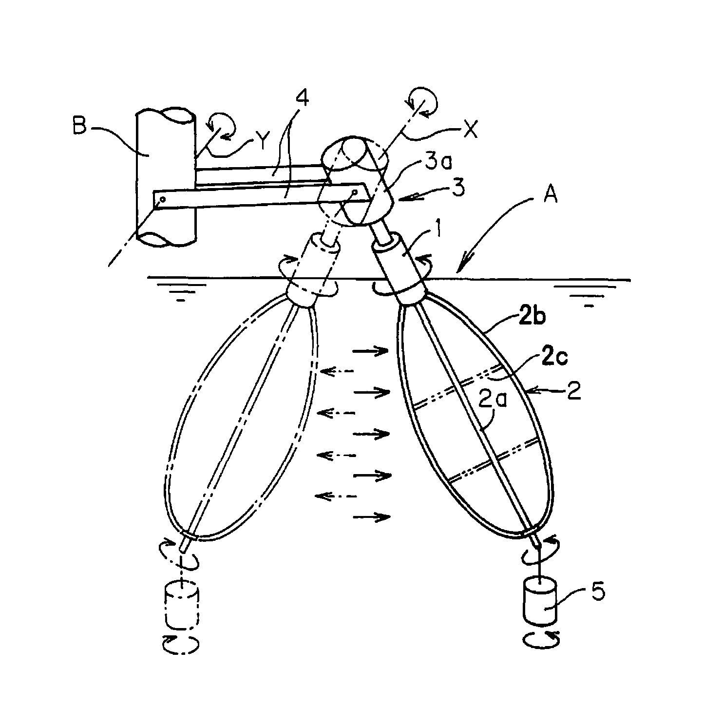
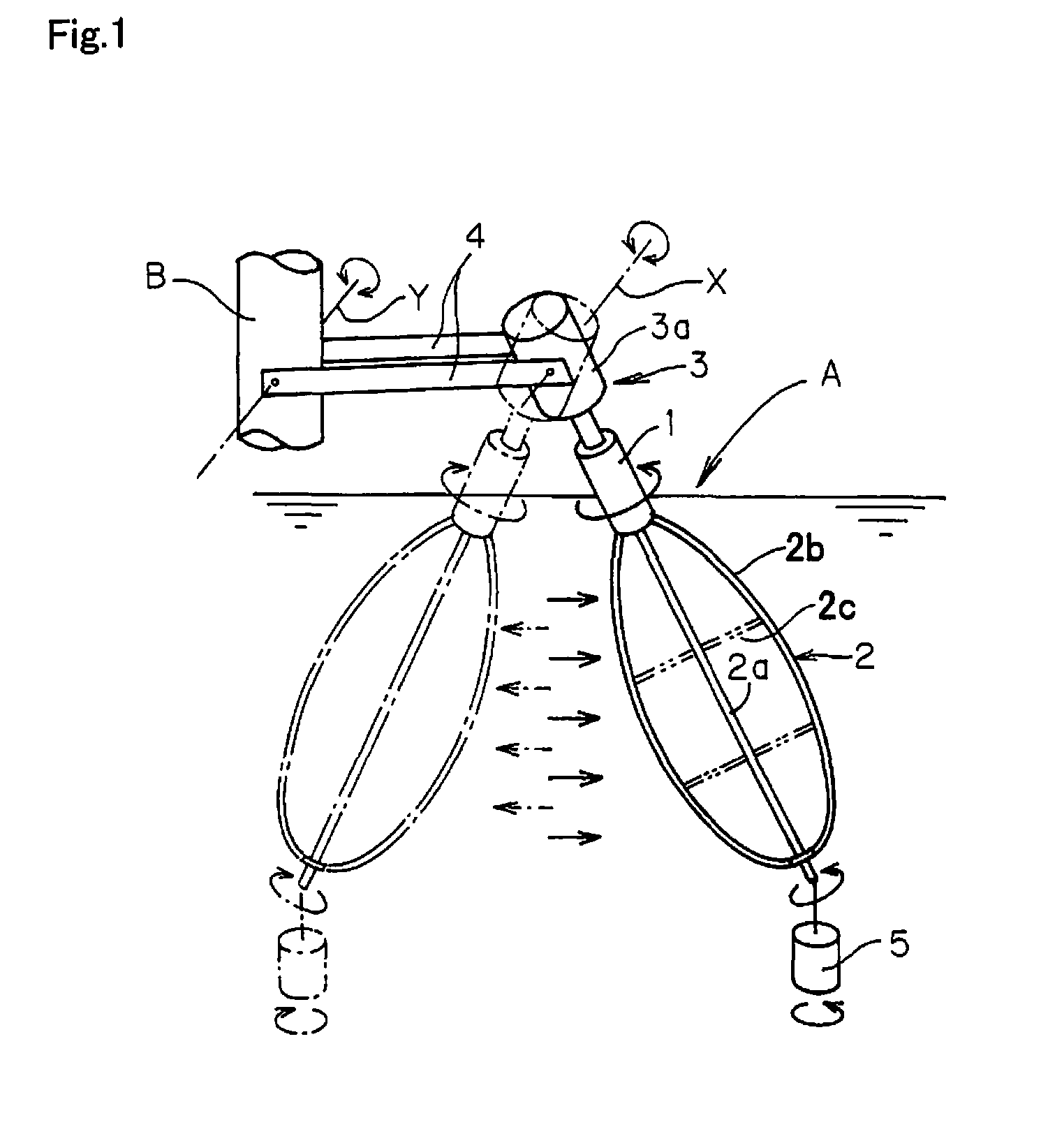
[0021]As shown in FIG. 1, a water current power generator A comprises a float 1 of cylindrical shape, a vertical-axis water turbine 2 fixed to the lower end of the float 1 and extending downward, a speed increasing gear train-power generator assembly 3 comprising a speed increasing gear train engaging the upper end of the float 1 and a power generator driven by the speed increasing gear train, and a pair of arm members 4 supporting a casing 3a of the speed increasing gear train-power generator assembly 3 rotatably around a horizontal axis X at one ends and supported rotatably around a horizontal axis Y extending parallel to the axis X by a fixed structure B located above a water current at the other ends. The speed increasing gear train and the power generator are not shown in FIG. 1.

[0022]A weight...


PUM


Abstract

An object of the present invention is to provide a natural energy extraction apparatus which can extract kinetic energies of river water currents or tidal water currents at various depth layers, and which is easy to attach to the fixed structure above water current. A natural energy extraction apparatus comprises a float, a vertical-axis water turbine fixed to the float and extending downward, a power transmission device engaging an upper end of the float and converting rotational kinetic energy of the float to driving torque for driven equipment, and arm members supporting the power transmission device rotatably around a horizontal axis at one ends and supported by a fixed structure above a water current rotatably around a horizontal axis at the other ends, wherein the float and the vertical-axis water turbine are located in a river water current or tidal water current.

Description

[0001]This is a National Phase Application in the United States of International Patent Application No. PCT / JP2012 / 066848 filed Jul. 2, 2012, which claims priority on Japanese Patent Application No. 2011-149017, filed Jul. 5, 2011. The entire disclosures of the above patent applications are hereby incorporated by reference.TECHNICAL FIELD[0002]The present invention relates to a natural energy extraction apparatusBACKGROUND ART[0003]Patent Document No. 1 discloses a water current power generator comprising a horizontal-axis water turbine forming a float, a speed increasing gear train-power generator assembly engaging one end of the horizontal-axis water turbine, a speed increasing gear train-power generator assembly engaging the other end of the horizontal-axis water turbine, and a pair of arm members, wherein each arm member is fixed to a casing of one of the speed increasing gear train-power generator assemblies at one end and supported rotatably around a horizontal axis by a fixed...

Claims


Application Information

Patent Timeline
Patent Type & Authority Patents(United States)
IPC IPC(8): F16D31/02F03B17/06F03B13/26
CPCF03B17/065F03B13/26F03B17/062Y02E10/223Y02E10/28Y02E10/38Y02E10/20Y02E10/30F03B13/10F03B17/06
Inventor AKIMOTO, HIROMICHI
Owner ALBATROSS TECH LLC
Why Eureka
Try Eureka