
Method for time synchronization in a communications network

a communication network and time synchronization technology, applied in the direction of synchronization signal speed/phase control, digital transmission, electrical equipment, etc., can solve the problems of insufficiently accurate time synchronization of slave nodes and flawed estimations, and achieve high precision and regularity of time synchronization in the communications network

Active Publication Date: 2016-03-15
SIEMENS AG
View PDF22 Cites 0 Cited by
  • Summary
  • Abstract
  • Description
  • Claims
  • Application Information

AI Technical Summary

Benefits of technology

[0011]It is therefore an object of the invention to provide a time synchronization in a communications network that is highly precise and regular across time.
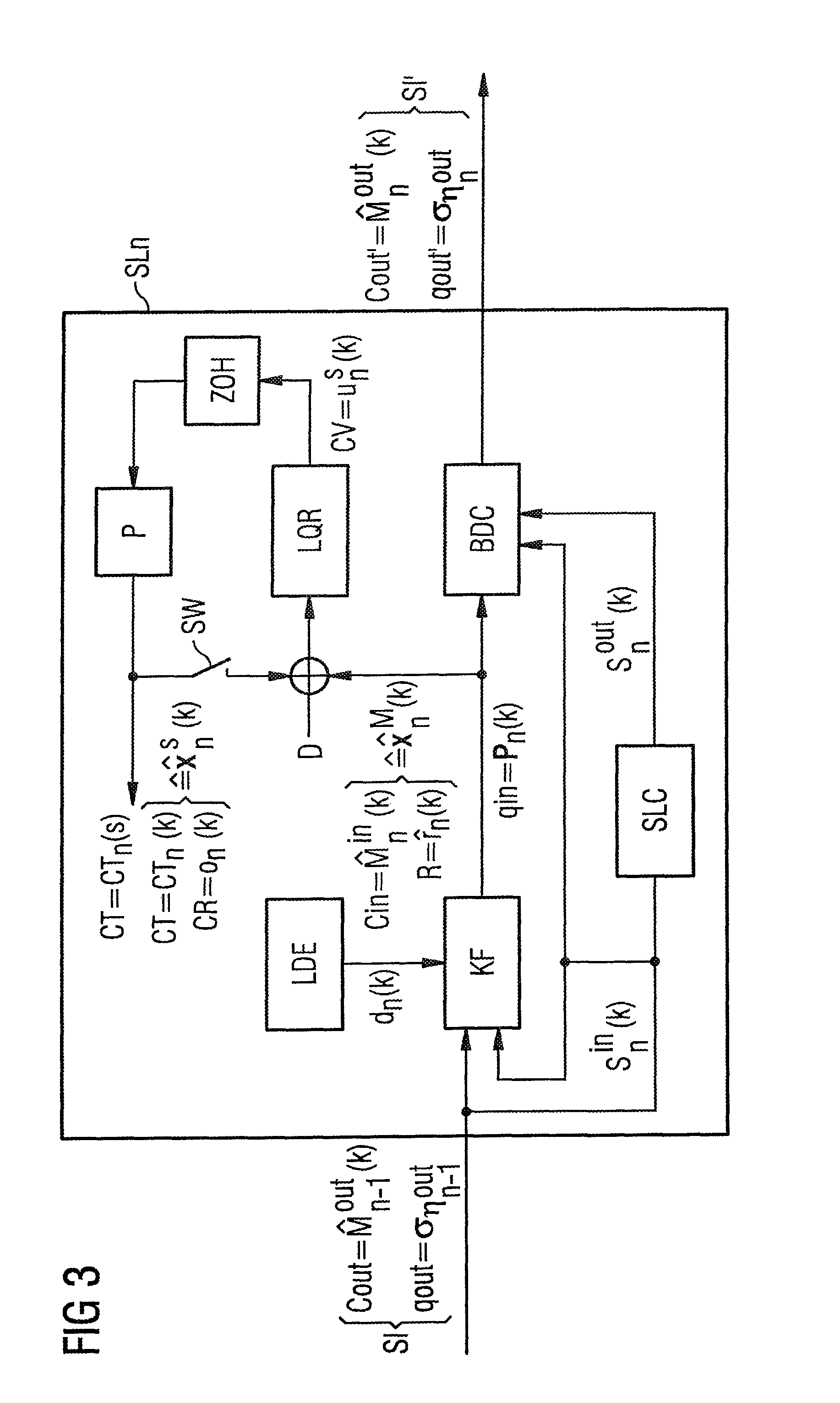
[0016]In a further preferred embodiment of the method in accordance with the invention, the manipulating variable is updated after every receipt of a synchronization message in the respective second node and supplied to the control loop. In this way, a continuous updating of the synchronization is assured. The manipulating variable is preferably supplied to the control loop via a ZOH (zero order hold) link, in order to illustrate the discrete updates on a continuous dynamic of the control loop.
[0021]In an especially preferred embodiment, the first cycle counter state and the compensation factor in Step i) are estimated by an estimation procedure in the form of a stochastic state estimator, and in particular a Kalman filter. The Kalman filter is generally known from the prior art, and estimates an unknown state of a system based on a corresponding state space model, which describes both the change in the state to be estimated (state transition model) and the relationship between the state and corresponding known observables (observation model). The combination of the Kalman filter and linear quadratic regulator provides a particularly good time synchronization.
[0027]In a further especially preferred embodiment of the method in accordance with the invention, the estimated first cycle counter state of the subsequent (i.e., retransmitted) synchronization message in a given second node and the associated stochastic variance are calculated with the aid of a node processing time from the first cycle counter state estimated by the Kalman filter and from the compensation factor estimated by the same means at the time of receipt of a synchronization message in the given second node and from the associated stochastic variance and are inserted into the subsequent (i.e., retransmitted) synchronization message, where the node processing time represents an estimated time lapse in the given second node between the receipt of the synchronization message in the given second node and the transmission of the subsequent synchronization message. The estimated delay time can be easily determined by a second node through its local second cycle counter states.

Problems solved by technology

One problem in synchronizing the clocks as described above is that, due to measurement errors in determining the time, varying frequencies of the individual clocks, random environmental effects, and unknown variations concerning the time delay between the receipt and transmission of synchronization messages, the internal clocks of the slave nodes cannot be sufficiently precisely attuned to the reference clock of the master node.
This compensation factor is estimated based on an inherently known method; this estimate is, however, flawed, because it does not model any variations of the clock frequency.

Method used


Image

  • Method for time synchronization in a communications network
  • Method for time synchronization in a communications network
  • Method for time synchronization in a communications network

Examples


Embodiment Construction

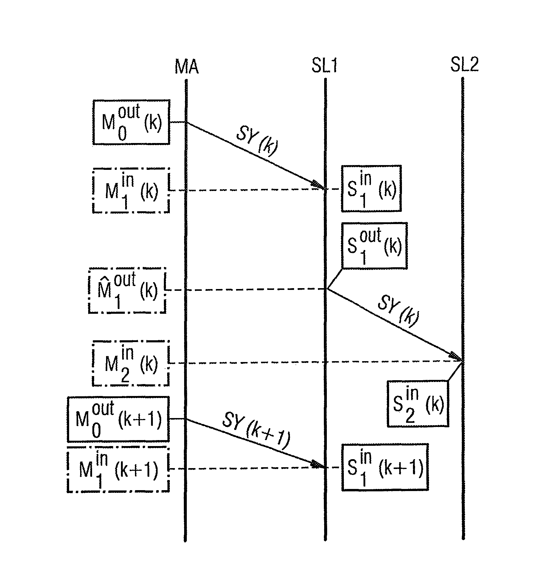
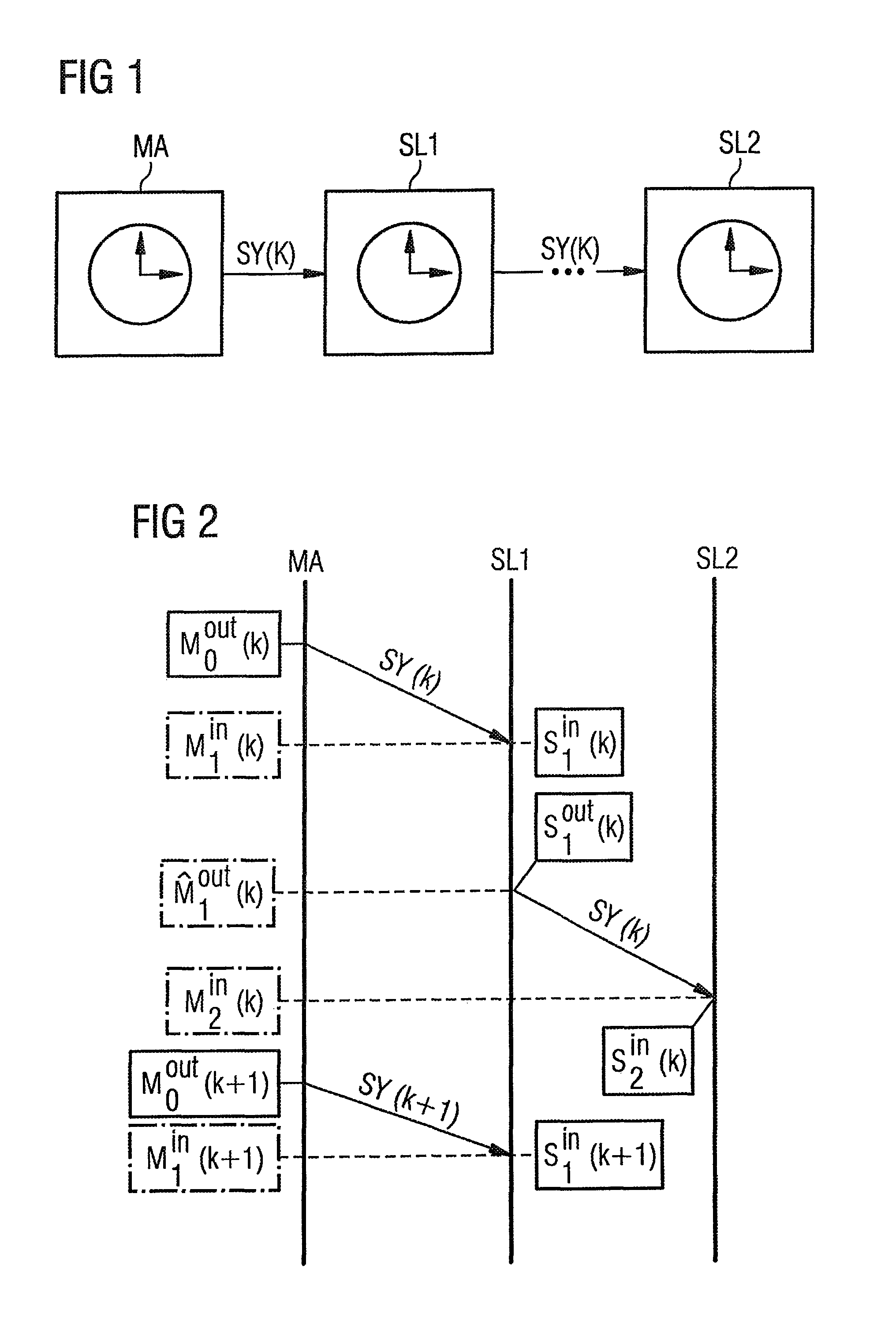
[0038]FIG. 1 depicts a chain of nodes in a communications network in which an embodiment of the method in accordance with the invention is being executed. The communications network comprises a first node in the form of a master node MA as well as multiple second nodes in the form of slave nodes, two slave nodes, SL1 and SL2, being depicted in FIG. 1. The master node MA contains a reference clock that generates a reference clock frequency. By contrast, the individual slave nodes SL1, SL2, etc. contain separate internal clocks generating corresponding internal clock frequencies. In the communications network in accordance with FIG. 1, a suitable time synchronization protocol, e.g., the PTP (Precision Time Protocol) protocol in accordance with the IEEE 1588 standard, is used to synchronize the internal clock of each slave node with the reference clock of the master node MA. To this end, synchronization messages SY(k) are transmitted from one node to another. Specifically, a synchroniz...


PUM


Abstract

A method for time synchronization in a communications network having multiple nodes, wherein the nodes comprise a first node and at least one second node, where the first node generates first cycle counter states according to a reference clock frequency and the second node or nodes each generate second cycle counter states according to an internal clock frequency, where a time synchronization is carried out in sequential synchronization cycles, in which synchronization messages originating from the first node are sequentially transmitted from one node to another node, and a synchronization message transmitted by a node contains information used for time synchronization in the at least one second node receiving the synchronization message such that a time synchronization is performed in a given second node based on an estimation of a first cycle counter state and a compensation factor in combination with a linear quadratic regulator.

Description

CROSS-REFERENCE TO RELATED APPLICATIONS[0001]This is a U.S. national stage of application No. PCT / EP2011 / 065126 filed 1 Sep. 2011. Priority is claimed on European Application No. 10179498.0 filed 24 Sep. 2010, the content of which is incorporated herein by reference in its entirety.BACKGROUND OF THE INVENTION[0002]1. Field of the Invention[0003]The invention relates to a method for time synchronization in a communications network, and a node in a communications network and a corresponding communications network.[0004]2. Description of the Related Art[0005]In many technical fields, communications networks are used to automatically execute distributed processes on a multitude of units. For industrial automation networks in particular, it is very important that the automatic processes be precisely coordinated with one another. To this end, the individual nodes in the communications network include suitable clocks, which are synchronized to a reference clock in a reference node. The ref...

Claims


Application Information

Patent Timeline
Patent Type & Authority Patents(United States)
IPC IPC(8): H04L7/04H04J3/06
CPCH04L7/04H04J3/0673H04J3/0667
Inventor OBRADOVIC, DRAGANSCHEITERER, RUXANDRAWOLFRUM, PHILIPPSTEINDL, GUNTER
Owner SIEMENS AG
Learn More