Liquid ejecting apparatus

a liquid ejecting and liquid technology, applied in the direction of printing, other printing apparatus, etc., can solve the problems of ink discharge outlet clogging, deposits formed in liquid receiving portions, etc., and achieve the effect of reducing the time of flushing

Active Publication Date: 2016-03-22
SEIKO EPSON CORP
View PDF8 Cites 2 Cited by
  • Summary
  • Abstract
  • Description
  • Claims
  • Application Information

AI Technical Summary

Benefits of technology

[0009]An advantage of some aspects of the invention is to provide a liquid ejecting apparatus that can suppress reductions in the maintenance function of the liquid receiving portion.
[0012]According to the abovementioned configuration, after flushing that ejects the plurality of kinds of liquids toward the liquid receiving portion from the liquid ejecting head as waste liquid has finished, in the liquid receiving portion, among the plurality of kinds of liquids for which flushing is performed, a liquid that is cured with most ease when the light is irradiated is covered with at least one different liquid that is cured with more difficulty than the liquid. Therefore, even in a case in which light that cures the liquids is incident upon the liquid receiving portion, such light is absorbed by at least one different liquid other than the liquid that is cured with most ease. That is, it is possible to suppress a concern that the liquid that is cured with most ease may be cured in the liquid receiving portion by such light, and for example, deposits may be formed. Therefore, it is possible to suppress reductions in the maintenance function of the liquid receiving portion that is capable of performing maintenance of the liquid ejecting head by receiving liquids that are ejected as waste liquid from the liquid ejecting head that ejects photocurable type liquid.
[0014]According to the abovementioned configuration, when light that cures the liquids is incident upon the liquid receiving portion after flushing has finished, among the plurality of kinds of liquids that are ejected into the liquid receiving portion as waste liquid, the light is absorbed by the liquid that is cured with most difficulty. Therefore, it is possible to further suppress a case in which photocurable type liquid that is received in the liquid receiving portion is cured.
[0016]According to the abovementioned configuration, when light that cures the liquids is incident upon the liquid receiving portion after flushing has finished, it is possible to further suppress a concern that, among the plurality of kinds of liquids that are ejected into the liquid receiving portion as waste liquid, the light may be absorbed by the liquid that is cured with most ease.
[0018]According to the abovementioned configuration, after flushing has finished, the probability that, in the liquid receiving portion, a liquid that is cured with ease may be covered with a liquid that is cured with difficulty, is increased. Therefore, when light that cures the liquids is incident upon the liquid receiving portion after flushing has finished, it is possible to further suppress a case in which the liquid that is cured with ease is cured by the light.
[0020]According to the abovementioned configuration, for example, when moving toward a position that opposes a medium from a position that opposes the liquid receiving portion, the liquid ejecting head can eject different ink other than the liquid that is cured with most difficulty into the liquid receiving portion before the liquid that is cured with most difficulty, and eject the liquid that is cured with most difficulty into the liquid receiving portion last. Therefore, it is possible to reduce the time of flushing.

Problems solved by technology

However, in such a case, a portion of the UV light, which is irradiated in the printing region toward the medium from the irradiation unit may be incident upon the liquid receiving portion that is disposed next to the printing region as leaked light from the printing region.
Therefore, deposits may be formed in the liquid receiving portion or clogging may occur in the ink discharge outlet as a result of ink (in particular, ink that is cured with relative ease) that is received in the liquid receiving portion being cured by the abovementioned leaked light.
Additionally, the technical problem that is outlined above is not limited to printers that eject UV curable type ink, and is a general problem that is common to liquid ejecting apparatuses that eject photocurable type liquid.

Method used


Image

  • Liquid ejecting apparatus
  • Liquid ejecting apparatus
  • Liquid ejecting apparatus

Examples


Embodiment Construction

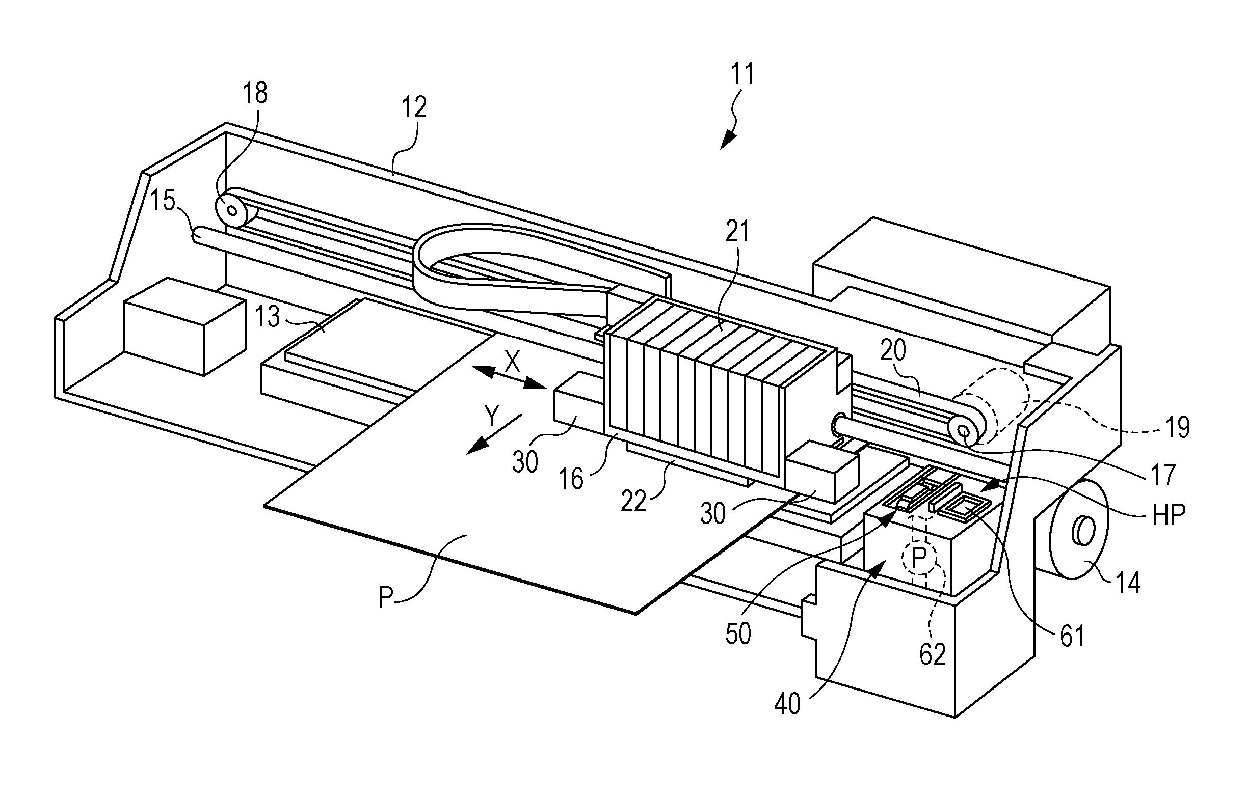
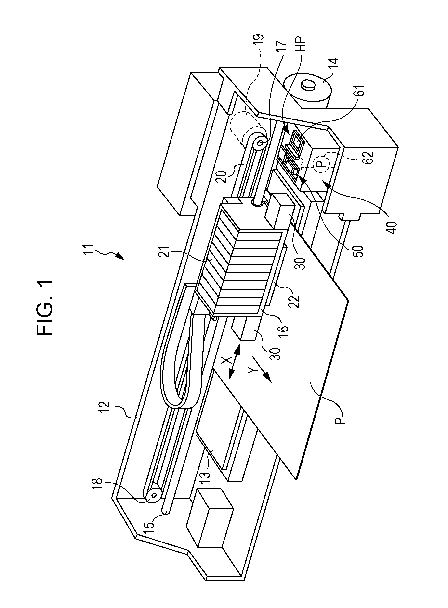
[0027]Hereinafter, an embodiment of the liquid ejecting apparatus as an ink jet type printer 11 will be described with reference to the drawings.

[0028]As shown in FIG. 1, in the printer 11, a rectangular plate-shaped supporting member 13 that extends in a longitudinal direction of a frame 12 is disposed in a lower portion inside the frame 12 that has a substantially rectangular box shape. Further, sheets P, as an example of a medium, are transported onto the supporting member 13 by a paper feed roller 14 that is disposed in a lower portion of a back surface of the frame 12. Therefore, in the inside of the frame 12, a region in which the supporting member 13 is disposed is a printing region.

[0029]Inside the frame 12, a guide shaft 15 is provided in a hanging manner above the supporting member 13 along the longitudinal direction of the supporting member 13. A carriage 16 is supported on the guide shaft 15 in a slidable manner along the longitudinal direction thereof.

[0030]A drive pull...


PUM


Abstract

A liquid ejecting apparatus includes a liquid ejecting head that ejects a plurality of kinds of photocurable type liquids, an irradiation unit that irradiates light that cures the liquids, a liquid receiving portion that is capable of receiving the liquids that are ejected from the liquid ejecting head, and a control unit that controls the ejection of the liquids from the liquid ejecting head. Among the plurality of kinds of liquids that are ejected, the control unit ejects a liquid that is cured with most ease when the light is irradiated before at least one different liquid other than the liquid in a case in which the plurality of kinds of liquids are ejected into the liquid receiving portion from the liquid ejecting head.

Description

BACKGROUND[0001]1. Technical Field[0002]The present invention relates to a liquid ejecting apparatus that ejects a photocurable type liquid onto a medium.[0003]2. Related Art[0004]In the related art, an ink jet type printer that is provided with a liquid ejecting head that ejects UV curable type ink that is cured by being irradiated with ultraviolet rays (hereinafter, also referred to as “UV” rays), and an irradiation unit that cures ink by irradiating a medium on which the ink has been ejected from the liquid ejecting head with UV light, is known as an example of a liquid ejecting apparatus (for example, JP-A-2005-125513).[0005]In addition, in this kind of printer, so-called flushing, which ejects ink from the liquid ejecting head as waste liquid on the basis of a control signal that is not related to printing, is performed as a kind of maintenance of the liquid ejecting head. As a liquid receiving portion that is used in flushing, for example, a liquid receiving portion that has a...

Claims


Application Information

Patent Timeline
Patent Type & Authority Patents(United States)
IPC IPC(8): B41J11/00B41J2/165
CPCB41J11/002B41J2/165B41J2/16505B41J2/16523B41J11/0021B41J11/00214
Inventor YOSHIDA, ATSUSHI
Owner SEIKO EPSON CORP
Why Eureka
Try Eureka