
LED dent repair and detail light

a technology of detail light and dent repair, which is applied in the field of illumination, can solve the problems of affecting the illumination pattern ofaffecting the illumination pattern, and the relatively thin sheet metal is susceptible to denting, etc., and achieves the effect of not affecting the paint on the painted work surface, enabling controllable spacing, and improving illumination pattern

Active Publication Date: 2016-03-22
PRO PDR SOLUTIONS INC
View PDF42 Cites 10 Cited by
  • Summary
  • Abstract
  • Description
  • Claims
  • Application Information

AI Technical Summary

Benefits of technology

The invention is an LED light module with multiple and parallel LED strips that can be controlled to be selectively lit or dark. The strips are mounted on a tray with a bottom surface and a side wall, and an elastomerically coated band is used to secure a flat diffuser panel to the lip of the tray. The LED light module provides rapid light to dark transitions that can be used to illuminate dents on a wide range of work surfaces without damaging the paint or surface. The light module is non-marring and easy to handle and place. The invention remains small and lightweight, which reduces the likelihood of damage to the work surface.

Problems solved by technology

When appropriate finishes are used, the sheet metal can have an extremely long life, even when fully exposed to an exterior environment.
Unfortunately, this same relatively thin sheet metal is susceptible to denting.
For example, objects may accidentally fall or be dropped onto the sheet metal, vehicles may accidentally bump an adjacent vehicle, shopping carts may roll across a parking lot into a vehicle, and storms may carry damaging hail or throw objects through the air.
These collisions will usually result in the visible deformation of the sheet metal.
However, such replacement can be extremely expensive, both in the purchase of replacement parts and in the labor involved.
Furthermore, depending upon the age and make or model, there may not even be a replacement available.
However, dent repair using filler is time-consuming, labor-intensive, and difficult to precisely match with the existing finish.
In other words, the filler texture is generally imperfect, and will not match that of the underlying sheet metal.
Unfortunately, this adds even more time and labor.
Further, even when the surface finish matches, the new paint will often still be extremely difficult to match to an existing paint.
While color is difficult enough, matching the more modern finishes that include metal flakes can be nearly impossible, owing to the variability in the amount of flakes in the paint at the time of original and repair application, and the variability of the orientation of the flakes in the cured paint.
Furthermore, at the time of repair or developing later, there may be microscopic separation between the filler and sheet metal.
This can lead to corrosion of the underlying metal, or cracking or separation of the filler subsequent to the repair.
As a result, filler does not normally have the long term durability of the original sheet metal and finish, particularly in the more harsh climates.
This greater distance helps to accommodate the large tubes and diffusion of the fluorescent phosphors, but unfortunately forces the technician to move back and forth across this distance to reposition the light stand.
While this may be minor for the repair of a single dent, when a vehicle has been hit many times by hail, this added time moving back and forth to readjust the light can be extremely time-consuming and frustrating.
Furthermore, prior art light stands such as illustrated by Hopf in the '862 patent and Merritt, each incorporated herein above, are very large and clumsy, and also as noted undesirably difficult since the light source is generally some distance from the technician.
There is a serious risk of damaging the vehicle finish if the light source is accidentally bumped or tipped, owing to the size and weight of the lights.
Furthermore, these stands are only useful for passenger vehicles, and are not well adapted to other types of vehicles, or for other non-vehicular applications that could otherwise benefit from PDR.
As noted, one of the challenges of an ideal PDR light source is the sharp transition from light to dark.
However, and as noted, the tubes are large, the light emanating therefrom diffuse, and the resulting fixture undesirably large.
However, these fail to teach how a module might be constructed to overcome the limitations of the prior art PDR illumination sources.
One of the issues with LED light sources is the lens affixed to the actual diode.
Unfortunately, the design of a lens to form a suitable PDR light is undesirably complex, and in addition to cost also undesirably adds weight.
Unfortunately, none of these illustrate or teach a non-marring mount that would be acceptable for use with a PDR illumination source.
While beneficial for the work light illustrated therein, there is no teaching for how this might be applied to a compact PDR illumination source.

Method used


Image

  • LED dent repair and detail light
  • LED dent repair and detail light
  • LED dent repair and detail light

Examples


Embodiment Construction

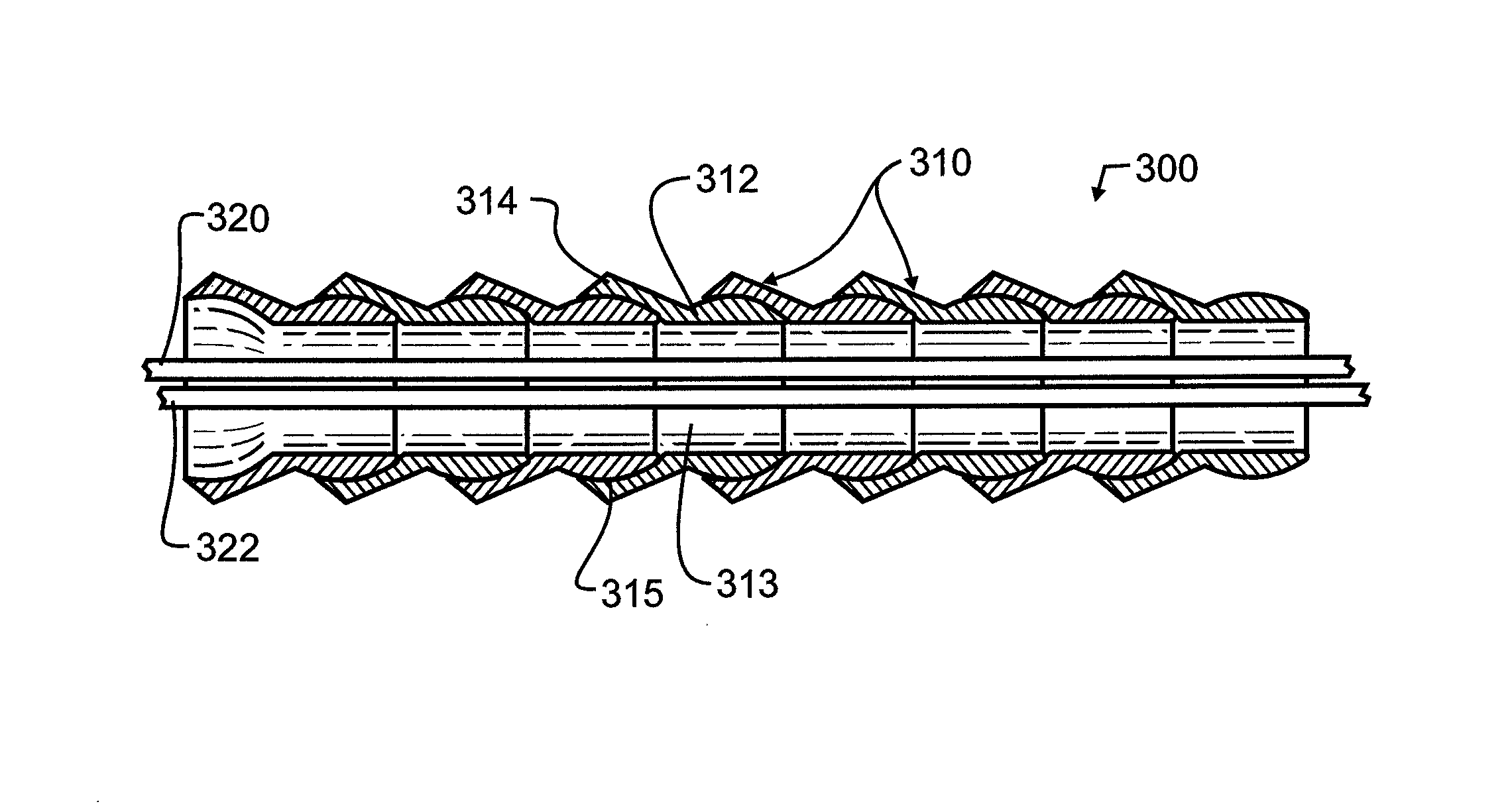
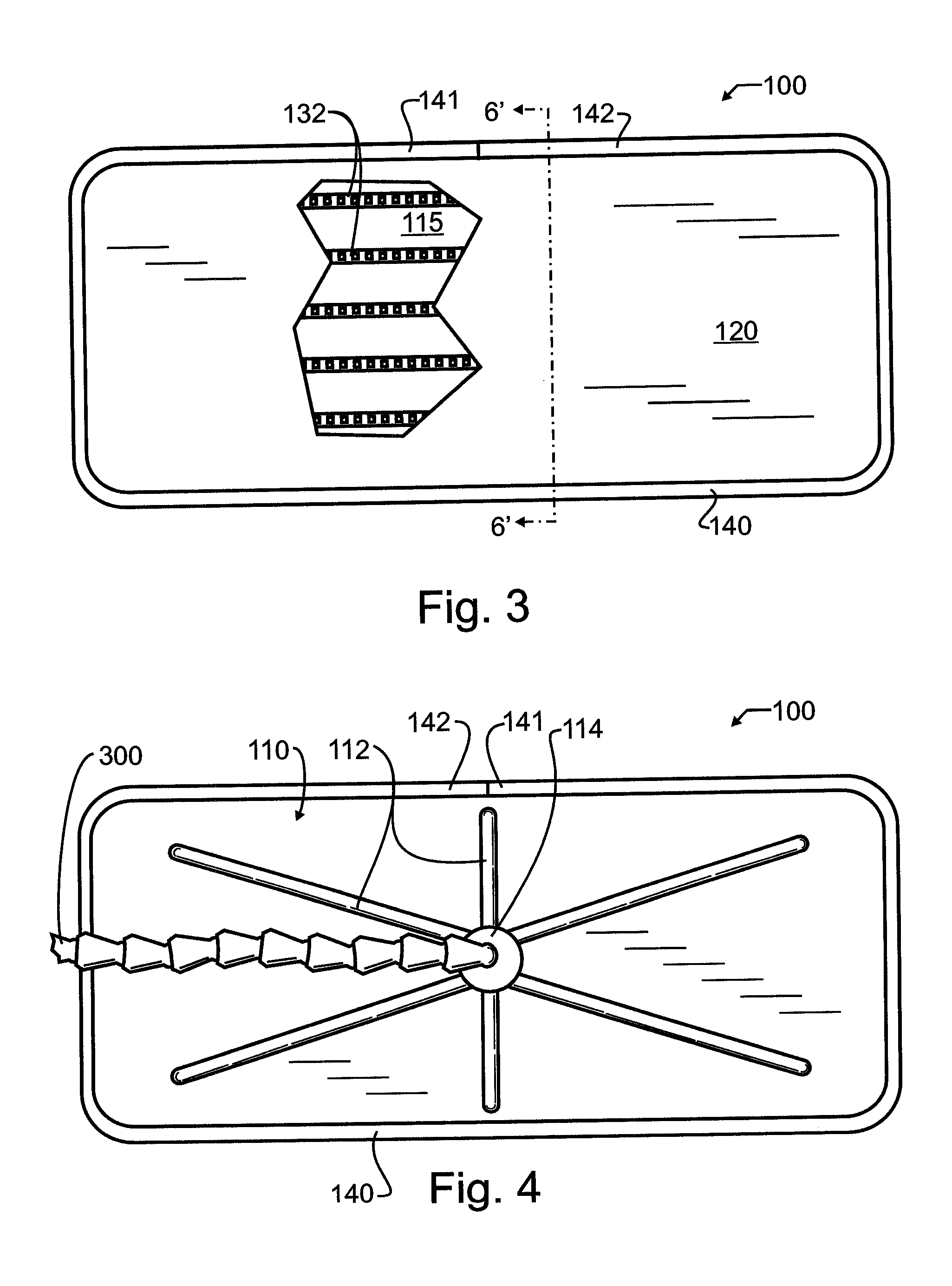
[0039]Manifested in the preferred embodiment as illustrated for exemplary purpose in FIG. 1, the present invention provides a paintless LED dent repair and detail light 10. Three separate modules make up the paintless LED dent repair and detail light 10, including an LED light module 100, a PDR light module power supply 200, and a ball and socket neck 300 coupling LED light module 100 to PDR light module power supply 200. Most preferably, ball and socket neck 300 is sufficiently stiff to rigidly support LED light module 100 from PDR light module power supply 200, even during minor vibration or physical disruption, until a manual force sufficient to overcome the static friction within ball and socket neck 300 is applied.

[0040]Ball and socket neck 300, illustrated in greater detail in FIG. 2, will for exemplary purposes comprise a plurality of repeating neck sections 310, each having a ball portion 312 which defines a somewhat spherical exterior, and a socket portion 314 defining a so...


PUM

PropertyMeasurementUnit
Strengthaaaaaaaaaa

Abstract

A paintless dent removal LED light module has a plurality of selectively illuminated LED strips. There is a small gap between a generally planar diffuser panel and the LED strips, so an image formed upon the diffuser panel has parallel bright strips separated by dark regions. The LED strips are supported upon a tray bottom surface, the tray also having a circumferential and vertically rising side wall, and a lip defining a second plane generally parallel with but displaced from the tray bottom. The diffuser panel rests upon the lip, and is secured by a band having an elastomeric exterior. The tray bottom may incorporate one or more ribs to provide additional strength and rigidity. A power supply has an entirely non-marring exterior with a supporting suction cup. A ball and socket neck having an entirely non-marring exterior mechanically and electrically couples the PDR light to the power supply.

Description

BACKGROUND OF THE INVENTION[0001]1. Field of the Invention[0002]This invention pertains generally to the field of illumination, and more particularly to a portable multiple light-emitting diode light source that is especially adapted to be adjustably supported directly upon a vehicle exterior. The invention has particular utility in the field of paintless dent removal, a specialized technique to repair dents without requiring painting the repaired area. Many different sheet metal objects may be repaired using this technique, the most common which is automobile bodies such as may have been damaged by hail or minor impacts. Other objects may be repaired as well, including without limitation, airplanes, recreational vehicles, metal trailers, boats, building siding, building doors and panels, and appliances.[0003]2. Description of the Related Art[0004]In the fabrication of many different apparatus, there is almost always consideration for weight, appearance, cost, strength, and durabili...

Claims


Application Information

Patent Timeline
IPC IPC(8): F21V7/04B21D1/10B23Q17/24F21K99/00F21V23/02F21V21/30F21V21/092F21Y105/00
CPCF21V21/30B21D1/10B23Q17/2404F21K9/30F21K9/50F21V21/0925F21V23/023F21Y2105/001F21S9/02F21V21/092F21V21/32F21V23/04B21D1/06F21Y2105/10F21Y2115/10F21K9/60F21V17/16F21W2131/40F21K9/66F21Y2105/16F21V3/02F21V21/29F21V23/0414
Inventor HULETT, WILLIAM, L.
Owner PRO PDR SOLUTIONS INC
Learn More