
Adaptive thermal control

a technology of adaptive thermal control and thermal control device, which is applied in the direction of process and machine control, semiconductor/solid-state device details, instruments, etc., can solve the problems of long delay in feedback and temperature control response time, significant device temperature changes, and the inability of a power following approach to adapt to the full test needs of the dut, so as to eliminate or reduce disadvantages and problems.

Active Publication Date: 2016-03-22
ADVANTEST CORP
View PDF4 Cites 20 Cited by
  • Summary
  • Abstract
  • Description
  • Claims
  • Application Information

AI Technical Summary

Benefits of technology

[0008]Accordingly, embodiments of the present invention provide systems and methods for adaptive thermal control for the DUT that eliminate or reduce the disadvantages and problems associated with the previously developed temperature control technologies for semiconductor devices.

Problems solved by technology

During testing, for example, the power level of the device under test (DUT) may vary, causing significant temperature changes of the device.
Some of the problems with these methods are long delays in the feedback and temperature control response time.
One deficiency of power following feedback is that it only follows the power variations not considering other predictive parameters such as frequency, doping levels, simulation results, outside temperature, etc.
Without the additional parameters it is impossible for a power following approach to adaptively respond to the full test needs of the DUT.
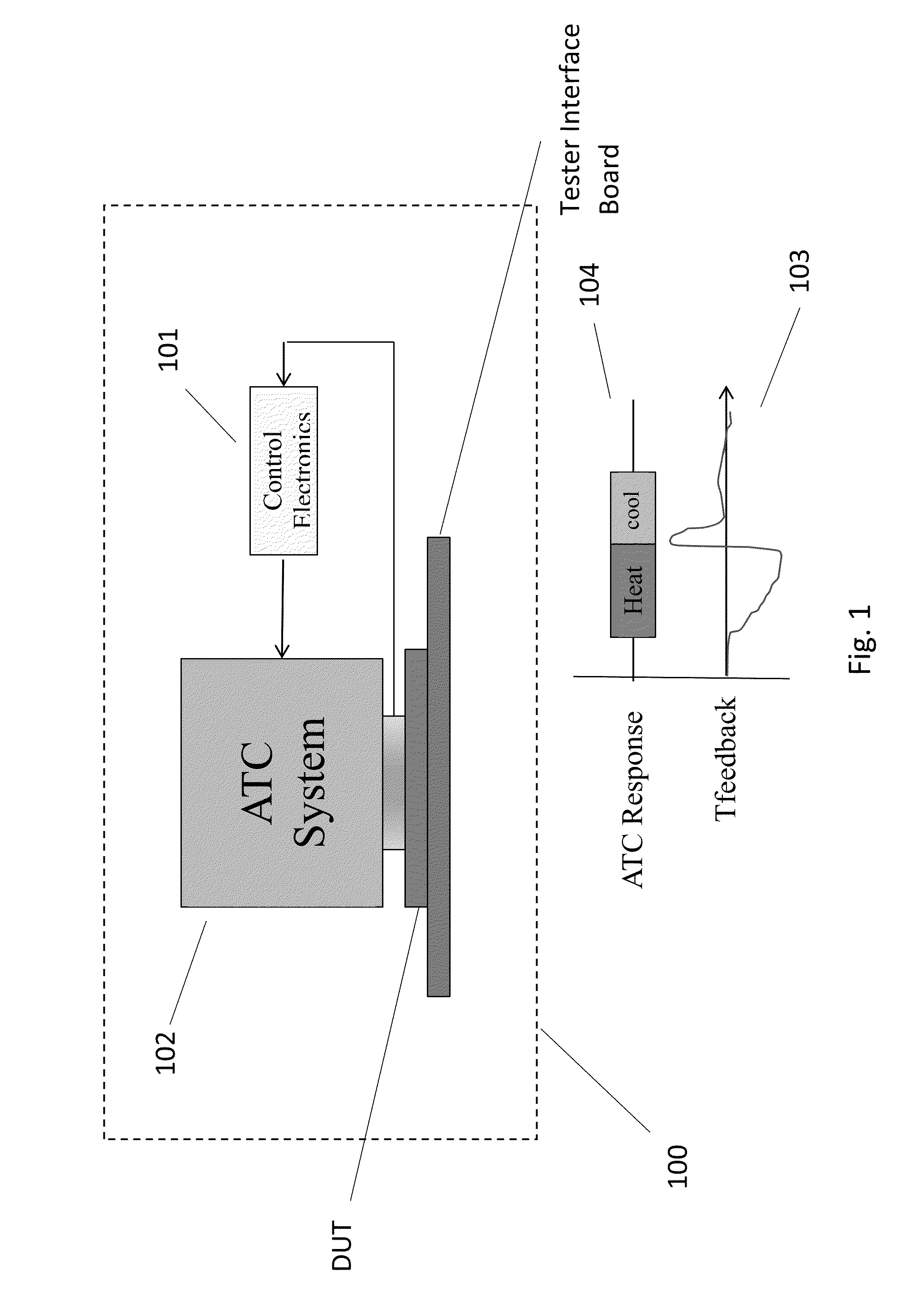
Another deficiency is that it does not control the slow response time of automatic thermal control (ATC) system, thus resulting in temperature over shoot and / or under shoot of the DUT.
The power following technique may result in excessive amounts of heating and cooling of the DUT in response to power changes, which is far from optimal.

Method used


Image

  • Adaptive thermal control
  • Adaptive thermal control
  • Adaptive thermal control

Examples


Embodiment Construction

[0025]Reference will now be made in detail to various embodiments of the present invention, examples of which are illustrated in the accompanying drawings. While the invention will be described in conjunction with these embodiments, it is understood that they are not intended to limit the invention to these embodiments. On the contrary, the invention is intended to cover alternatives, modifications and equivalents, which may be included within the spirit and scope of the invention as defined by the appended claims. Furthermore, in the following detailed description of the invention, numerous specific details are set forth in order to provide a thorough understanding of the invention. However, it will be recognized by one of ordinary skill in the art that the invention may be practiced without these specific details. In other instances, well known methods, procedures, components, and circuits have not been described in detail as not to unnecessarily obscure aspects of the invention.

A...


PUM


Abstract

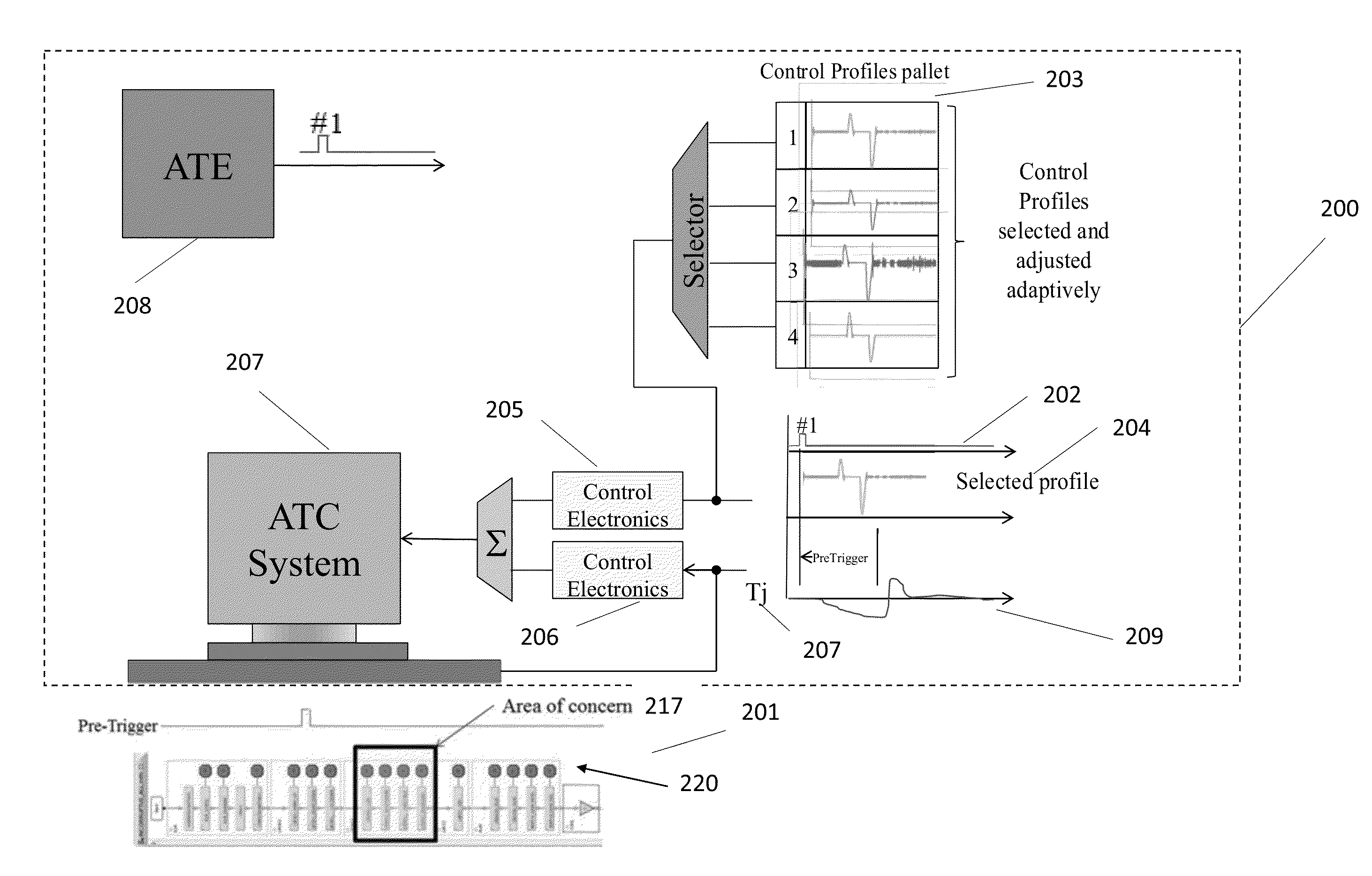
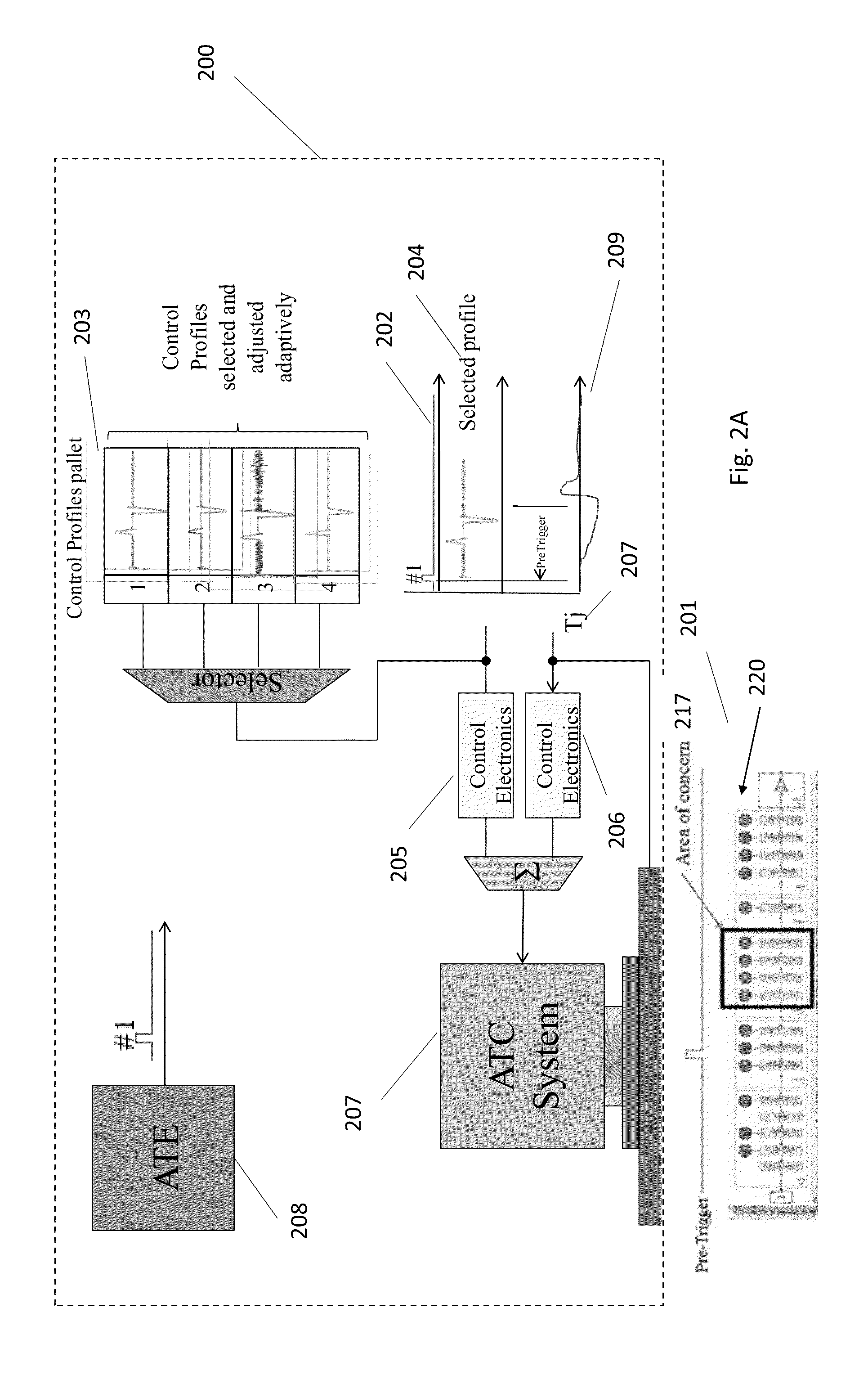
An adaptive thermal control system maintains and regulates an accurate and stable thermal environment for a device under test. The adaptive thermal control system includes (i) pre-trigger communications from automatic test equipment (ATE) to automatic thermal control (ATC) allowing slow-responding ATC to start responding to an imminent thermal change before the thermal change occurs, (ii) a control profile which indicates to the ATC, prior to anticipated thermal change, that a change is imminent and the nature of the change over time. The generation and fine-tuning of the control profile can be done by two different methods (i) with the semi-automatic approach the tester does some pre-tests in order to determine a typical response profile which the test program then adjusts using adaptive techniques, (ii) With the fully automatic adaptive circuitries same typical response profile is algorithmically adjusted and utilized to control the ATC.

Description

RELATED APPLICATIONS[0001]This application claims priority to U.S. Provisional Patent Application 61 / 774,500, entitled, “Adaptive Thermal Control,” filed 7 Mar. 2013, by Dave Armstrong and Mike Callaway, attorney docket number ATST-JP0097.A, which is hereby incorporated herein by reference in its entirety.FIELD OF INVENTION[0002]Embodiments of the present invention relate to the field of semiconductor devices, and temperature control. More specifically, embodiments of the present invention relate to systems and methods for thermal control during device testing.BACKGROUND[0003]In testing semiconductor devices, it is important to control and maintain an accurate stable thermal environment. Semiconductor devices generally undergo a variety of tests to insure proper operation. During testing, for example, the power level of the device under test (DUT) may vary, causing significant temperature changes of the device. In dealing with this problem there are various conventional techniques t...

Claims


Application Information

Patent Timeline
Patent Type & Authority Patents(United States)
IPC IPC(8): G05D23/20G01R31/28G05D23/19H01L23/473
CPCG05D23/1919G01R31/2874H01L23/4735H01L2924/00H01L2924/0002
Inventor ARMSTRONG, DAVID H.CALLAWAY, MIKE
Owner ADVANTEST CORP
Learn More