Electronic component assembly structure and electrical junction box

a technology of electronic components and assembly structures, applied in the direction of cable junctions, relays, coupling device connections, etc., can solve the problems of easy accumulation of heat in the main body of components, and achieve the effects of suppressing vibration, reducing the burden on the terminal fitting, and suppressing the vibration of electronic components

Active Publication Date: 2016-03-22
YAZAKI CORP
View PDF25 Cites 13 Cited by
  • Summary
  • Abstract
  • Description
  • Claims
  • Application Information

AI Technical Summary

Benefits of technology

[0011]In this way, in the invention, the electronic component is essentially used in which the lead terminal extends along the side surface of the component main body. Then, when the component main body and the lead terminal of the electronic component are respectively inserted and accommodated in the first housing chamber and the second housing chamber of the housing member, a distance between the height position of the center of gravity of the component main body and the height position of the spring portion in the insertion direction of the electronic component may be shortened. Thus, since it is possible to effectively suppress a vibration mainly in a direction intersecting the insertion direction of the electronic component and to reduce a burden on the terminal fitting supporting the component main body, it is possible to suppress the vibration of the electronic component with a simple configuration without increasing the size of the terminal fitting or the housing member.
[0012]Incidentally, the component main body radiates heat when the electronic component is operated. For that reason, there is a need to release the heat generated from the component main body to the outside in order to satisfactorily maintain the function of the electronic component. However, the heat is easily accumulated in the component main body when the component main body is surrounded by the wall portion.
[0014]Accordingly, when the locking protrusion is locked to the penetration groove, the heat of the component main body is radiated to the outside from a gap formed in the penetration groove so as to suppress an increase in the temperature of the component main body. For this reason, the function of the electronic component may be satisfactorily maintained. Further, the locking protrusion of the component main body is locked to the penetration groove so as to hold the component main body in the wall portion of the first housing chamber. For this reason, the rattling of the component main body may be suppressed, and hence the vibration of the electronic component may be further suppressed.
[0016]It is preferable that a part or the entirety of the base end of the lead terminal in the electronic component is coated by an insulation member. Accordingly, it is possible to prevent a trouble such as an electric shock and a short circuit in the lead terminal.
[0018]Accordingly, since the component main body is surrounded by the first housing chamber and the cover member, it is possible to protect the component main body from the outside. Further, since it is possible to suppress the vibration of the component main body by the cover member, it is possible to reduce a burden on the terminal fitting. In this case, the cover member is formed so as to press the component main body accommodated in the first housing chamber. Accordingly, it is possible to more reliably suppress the vibration of the electronic component.
[0020]Accordingly, since the electronic component may be surrounded by the housing member and the side wall of the frame, it is possible to prevent water from adhering to the electronic component and to suppress the vibration of the electronic component. Further, since the insertion opening of the housing member is disposed so as to face the side wall of the frame, it is possible to shorten the dimension of the frame in the thickness direction and hence to decrease the installation space.

Problems solved by technology

However, the heat is easily accumulated in the component main body when the component main body is surrounded by the wall portion.

Method used


Image

  • Electronic component assembly structure and electrical junction box
  • Electronic component assembly structure and electrical junction box
  • Electronic component assembly structure and electrical junction box

Examples


Embodiment Construction

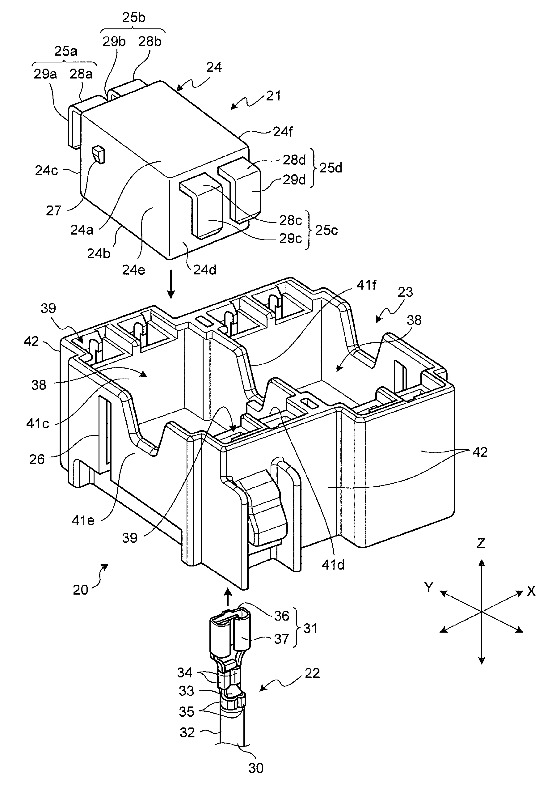
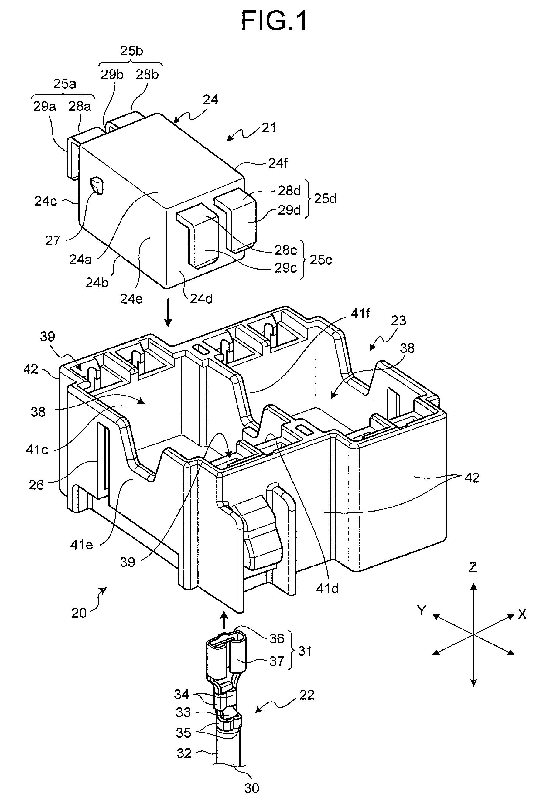
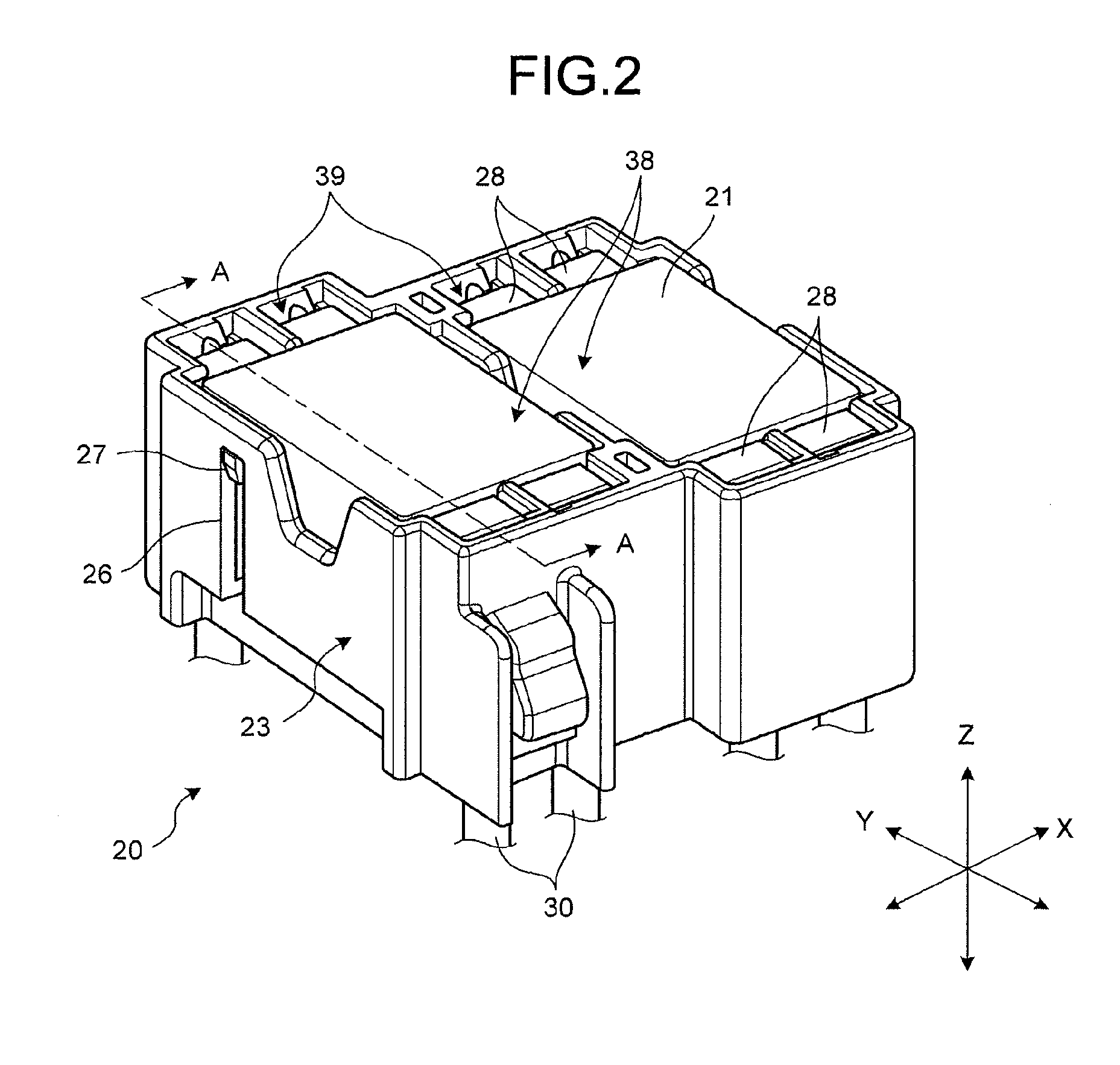
[0038]Hereinafter, an embodiment of a relay module including an electronic component assembly structure according to the invention will be described with reference to the drawings. In the embodiment, a relay module will be described in which a relay is used as an electronic component and the relay is accommodated in a housing member. However, an electronic component assembly structure according to the invention may be also, of course, applied to an electronic component other than the relay.

[0039]In the embodiment, the application example of the relay module is not particularly limited. However, a case may be supposed in which the relay module is used in electronic equipment controlling a connection state between an electric component and a power supply in a mobile vehicle such as an automobile. Specifically, a case may be supposed in which the relay module is assembled to, for example, an electrical junction box (a junction box) provided between a battery and an electric component m...


PUM


Abstract

An electronic component including a lead terminal is inserted into a housing member, and the lead terminal is fitted to a terminal fitting held by the housing member, so that the electronic component is assembled to the housing member. The lead terminal includes a connection portion which is continuous to a base end and is suspended along a side surface of a component main body. The housing member includes a first housing chamber which accommodates the component main body and a second housing chamber which holds the terminal fitting, the first housing chamber is surrounded by a frame-shaped wall portion. The terminal fitting is disposed so as to face the side surface of the component main body, in which a spring portion pressing the connection portion is accommodated in the first housing chamber, with the wall portion interposed therebetween.

Description

CROSS-REFERENCE TO RELATED APPLICATION[0001]This application is a continuation application of International Application PCT / JP2014 / 056698, filed on Mar. 13, 2014, which claims priority from Japanese Patent Application No. 2013-052460, filed on Mar. 14, 2013, the contents of all of which are incorporated herein by reference in their entirety.BACKGROUND OF THE INVENTION[0002]1. Field of the Invention[0003]The present invention relates to an electronic component assembly structure and an electrical junction box, and particularly, to an electronic component assembly structure provided in an electrical junction box mounted on a mobile vehicle such as an automobile.[0004]2. Description of the Related Art[0005]Generally, a mobile vehicle such as an automobile is equipped with an electrical junction box which accommodates an electronic component such as a relay for controlling a connection between a power supply and an electric component (see Japanese Patent Application Laid-open No. 2010-2...

Claims


Application Information

Patent Timeline
Patent Type & Authority Patents(United States)
IPC IPC(8): H01H9/02H01R9/24H01R33/975H02G15/10
CPCH01H9/02H01R9/2408H01R9/2416H01R33/975H02G15/10H01H2223/044H01H2050/049H01H50/048
Inventor KAWAMURA, YUKIHIROYAMADA, HIROAKI
Owner YAZAKI CORP
Why Eureka
Try Eureka