Electron multiplier and photomultiplier including the same

a technology of photomultipliers and multipliers, applied in the direction of multiplier dynodes, multiplier electrode arrangements, electric discharge tubes, etc., can solve problems such as unwanted luminescence, and achieve the effect of suppressing luminescence nois

Active Publication Date: 2016-03-22
HAMAMATSU PHOTONICS KK
View PDF37 Cites 3 Cited by
  • Summary
  • Abstract
  • Description
  • Claims
  • Application Information

AI Technical Summary

Benefits of technology

[0008]The present invention has been accomplished in view of the above-described problem and an object of the present invention is to provide an electron multiplier with a dynode structure for effectively suppressing the luminescence noise, even in compact size, and a photomultiplier including the same.

Problems solved by technology

For this reason, when the photomultiplier is constructed in compact size, generated secondary electrons impinge on the insulating substrate to cause unwanted luminescence, which becomes a noise source.

Method used


Image

  • Electron multiplier and photomultiplier including the same
  • Electron multiplier and photomultiplier including the same
  • Electron multiplier and photomultiplier including the same

Examples


Embodiment Construction

[0042]Each of embodiments of the dynodes, electron multiplier, and photomultiplier according to the present invention will be described below in detail with reference to the accompanying drawings. In the description of drawings identical or equivalent portions will be denoted by the same reference signs, without redundant description.

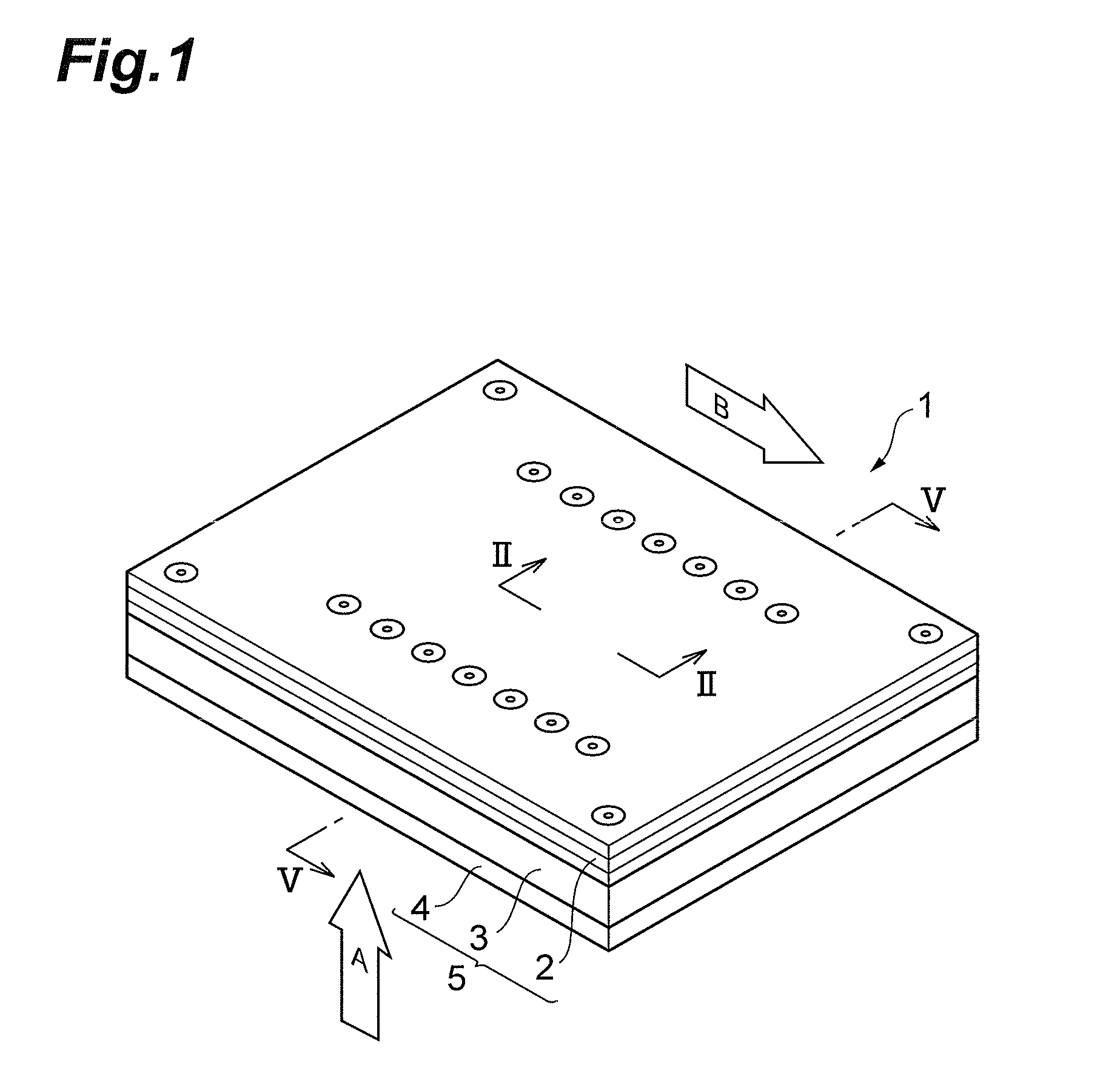
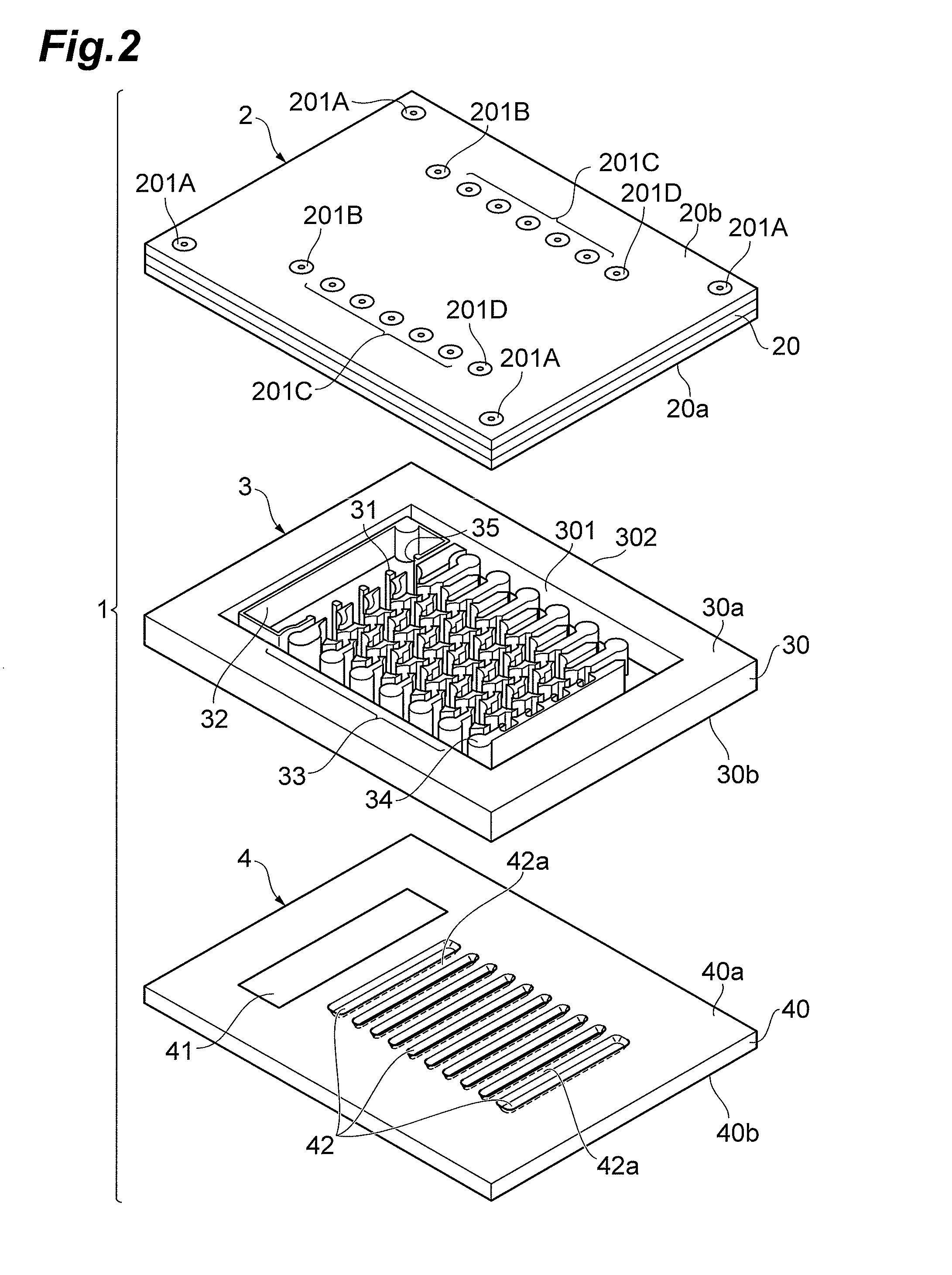
[0043]FIG. 1 is a perspective view showing a configuration of an embodiment of the photomultiplier according to the present invention and FIG. 2 an exploded perspective view of the photomultiplier 1 shown in FIG. 1.

[0044]The photomultiplier 1 shown in FIG. 1 is a photomultiplier tube with a transmissive photocathode and is provided with a housing 5 as an envelope composed of an upper frame (second substrate) 2, a sidewall frame 3, and a lower frame (first substrate) 4 opposed to the upper frame 2 with the sidewall frame 3 in between. This photomultiplier 1 is an electron tube in which a direction of incidence of light to the photocathode intersects with...


PUM


Abstract

The present invention relates to an electron multiplier and others to effectively suppress luminescence noise, even in compact size, in which each of multistage dynodes has a plurality of columns each having a peripheral surface separated physically, and in which each column is processed in such a shape that an area or a peripheral length of a section parallel to an installation surface on which the electron multiplier is arranged becomes minimum at a certain position on the peripheral surface in the column of interest.

Description

CROSS-REFERENCE TO RELATED APPLICATION[0001]This application claims the priority to Provisional Application No. 61 / 492,857 filed on Jun. 3, 2011 by the same Applicant, the contents of which are incorporated herein by reference in its entirety.BACKGROUND OF THE INVENTION[0002]1. Field of the Invention[0003]The present invention relates to a photomultiplier to detect incident light from the outside and an electron multiplier applicable to a wide variety of sensor devices including the photomultiplier.[0004]2. Related Background Art[0005]Compact photomultipliers have been developed heretofore using the microfabrication technology. For example, there is a known planar photomultiplier in which a photocathode, dynodes, and an anode are arranged on an optically-transparent insulating substrate (cf. U.S. Pat. No. 5,264,693). This structure realizes detection of weak light and achieves miniaturization of the device as well.SUMMARY OF THE INVENTION[0006]The Inventor investigated the aforement...

Claims


Application Information

Patent Timeline
Patent Type & Authority Patents(United States)
IPC IPC(8): H01J43/22
CPCH01J43/22H01J43/10
Inventor SHIMOI, HIDEKIKYUSHIMA, HIROYUKIINOUE, KEISUKE
Owner HAMAMATSU PHOTONICS KK
Why Eureka
Try Eureka